
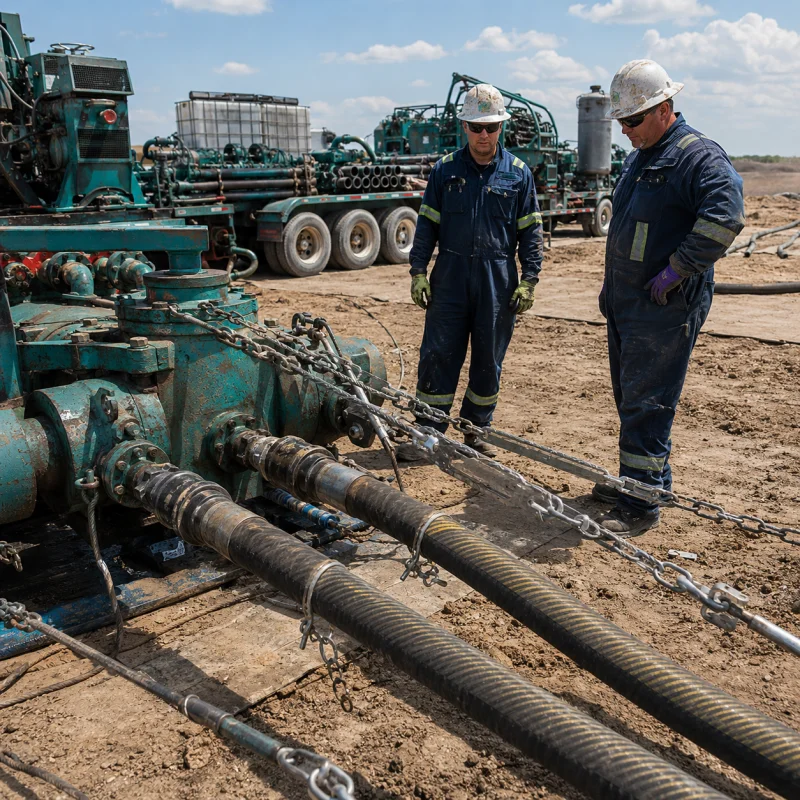
A high-pressure frac hose should never be treated as a flexible substitute for any line that happens to reach between two pieces of equipment. It is a pressure-containing assembly with a defined working envelope, rigid end connections and stored-energy hazards.
Safe use depends on knowing exactly which assembly is on the pad, installing it without twist or an over-tight bend, inspecting the whole hose, and removing it from service when its condition is uncertain.
This high-pressure frac hose safety guide is written for field personnel, supervisors, maintenance teams and buyers who need a practical pre-job and in-service reference. It covers identification, frac hose inspection and routing, restraints, stop-work criteria, testing boundaries and records.
It does not replace the manufacturer’s instructions, the approved site procedure, an engineering review or the risk controls required for a specific frac spread.
Key Safety Takeaways
- Identify the hose by model, serial number and controlled records before it enters service. Unknown identity means unknown limits.
- Use the maximum expected working and transient pressure for selection. A proof or burst value is not an operating pressure.
- Keep the hose above its documented minimum bend radius, prevent torsion, support heavy ends and protect the cover from rubbing, dragging, impact and traffic.
- Use restraints and exclusion zones defined by the approved system design and site risk assessment. A generic whip check is not automatically suitable for every high-pressure assembly.
- Remove or quarantine a hose for leakage, exposed reinforcement, blisters, permanent kinks, crushing, coupling movement, heat damage, chemical incompatibility, lost traceability, unauthorized repair or an unreviewed pressure excursion.
- Never use a hand or another body part to locate a high-pressure pinhole leak. Stop pumping, isolate the source and fully depressurize first.
Scope of This Safety Guide
“Frac hose” describes several products that may appear on the same location. They are not interchangeable. AlienFrac’s frac hose range separates water-transfer, high-pressure pumping and acid-service paths. Use the current high-pressure frac hose page as the product-family starting point, then confirm the exact offered assembly; the safety controls must follow the actual duty and approved limits.
| Hose duty | Typical role | Primary safety question |
| High-pressure frac hose | Flexible treatment line between pumps, manifolds or other pressure-system equipment | Does the complete assembly match pressure, transients, fluid, temperature, routing and both end interfaces? |
| TPU layflat water-transfer hose | High-volume transfer of compatible water or other approved fluid | Is the transfer pressure, chemistry, route and deployment method within the product limits? |
| Acid-service frac hose | Transfer or high-pressure service involving a defined acid/chemical recipe | Are the tube, seals, reinforcement and ends compatible with the exact chemistry and exposure? |
| API 16C choke-and-kill hose | Choke-and-kill service within the applicable system and qualification scope | Is the assembly actually specified and documented for API 16C service? |
API 16C should not be used as a blanket standard for every frac hose. It applies where the assembly is genuinely part of a choke-and-kill application. Review AlienFrac’s flexible choke-and-kill hose separately when that is the required duty. For acid service, complete a separate acid fracturing hose requirements review before approving the hose.
Information to Confirm Before Installation
Do not start with a pressure class alone. Build a one-page installation record that connects the hose tag to the actual operating envelope and route. At minimum, confirm the following:
- Manufacturer, product family, model or part number, serial number and date/status of the controlling record.
- Maximum allowable working pressure for the complete assembly and the highest expected pressure transient or surge.
- Fluid composition, additives, solids or proppant, concentration, temperature and credible cleaning fluids.
- Hose ID, finished length, length-measurement datum, minimum bend radius and any static/dynamic routing limits.
- End A and End B: connection type, size, pressure class, seal, material, orientation and verified mating equipment.
- Support, restraint, abrasion protection, lifting/handling provisions and the approved exclusion-zone plan.
- Required inspection, pressure-test or recertification procedure and the acceptance criteria for this exact assembly.
- Data sheet, assembly drawing, test record, traceability file and any project-specific certificate or witness requirement.
The broader oilfield hose specification guide is useful when ID, OD, temperature and pressure inputs still need to be defined. The assembly rating is limited by the lowest-rated component in the pressure path; a higher-rated hose body does not upgrade a lower-rated connector, adapter, seal or mating component.
Pre-Job Inspection Checklist
Inspect the clean, depressurized hose in adequate light and compare it with its controlled record. Walk the full length; the end areas deserve extra attention, but they are not the only places where damage develops.
Identification and Rating
- Layline, tag or data plate is present and legible.
- Model, serial number and assembly length match the hose register and job package.
- Working-pressure and temperature limits cover the planned duty, including known transients.
- Fluid and cleaning-media compatibility has been confirmed for the complete assembly.
Hose Body and Cover
- No leaks, wet spots, blisters, soft areas, bulges, cuts, gouges or deep abrasion.
- No exposed, broken, corroded or displaced reinforcement.
- No permanent kink, flattening, crushing, heat damage, burn marks or unusual stiffness.
- No evidence of chemical swelling, delamination or cover deterioration.
Ends, Route and Controls
- No coupling movement, end separation, cracks, deformation, damaged seal face or severe corrosion.
- Mating connections are clean, correctly identified, aligned and rated for the duty.
- The proposed route respects minimum bend radius and does not force a bend directly behind a coupling.
- The hose is not twisted, stretched tight, pinched, unsupported at a heavy end or rubbing another line.
- Approved restraints, supports, guards and exclusion-zone controls are installed as the job plan requires.
Stop-work rule: If the hose identity, condition, pressure history or installation cannot be verified, quarantine it. Do not use system pressure as the inspection method.
Installation and Routing
Protect the Flexible Section Behind Each Coupling
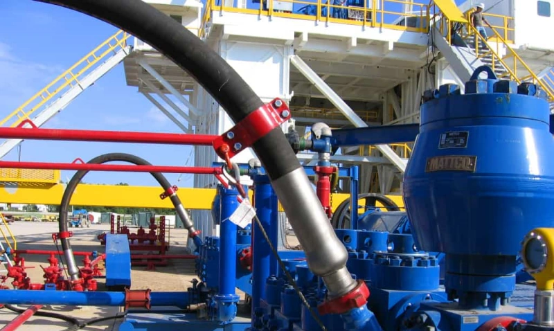
A rigid coupling cannot follow the hose bend. If the route turns too soon, the first flexible section carries concentrated bending and side load. Provide enough straight, supported transition for the installed end geometry, and use the documented minimum bend radius for the selected assembly. The minimum bend radius guide explains how to measure and check the bend, but the controlled assembly value takes priority.
Prevent Twist and Misalignment
Set the hose in its natural plane before the final connection is made. Do not use the hose to pull two misaligned items into position. Marking a straight reference line along the cover can make torsion easier to spot during rig-up. Where a swivel or angled interface is proposed, confirm that it is approved for the assembly and that its pressure rating does not reduce the system limit.
Support Weight and Control Abrasion
Support heavy unions, flanges and hubs so their weight is not carried by a short hose section. Keep the cover clear of sharp edges and hot surfaces. Prevent hose-to-hose rubbing, dragging over gravel and contact with vibrating equipment. Use an engineered crossing or barrier where vehicles must pass; never assume the cover alone can withstand wheel loading.
Connections, Restraints and Exclusion Zones
Specify both ends before production and verify the mating components before rig-up. AlienFrac’s frac hose connection types guide provides the End A/End B inputs for hammer unions, flanges and hubs. Restraints must be selected, positioned and anchored under the approved system design. Their rating, geometry and attachment points should match the hose, connection and credible failure motion.
Set the exclusion zone from the site risk assessment, line layout, pressure, fluid and failure consequences. Keep personnel out while the system is pressurized unless a written task and control plan specifically permits entry. Do not stand over a hose, straddle it, step between pressurized lines or position yourself in front of an end connection.
Operating Controls During Pumping
- Increase pressure under the approved startup procedure and watch from a protected location outside the exclusion zone.
- Monitor pressure, unexpected pulsation, movement, support condition and signs of leakage without approaching the line.
- Do not tighten, realign, clamp, restrain or otherwise adjust a pressurized hose assembly.
- Control valve operation and pump changes to reduce avoidable transients; investigate any unexpected pressure excursion.
- Stop the job if the hose moves abnormally, a restraint shifts, a support fails, leakage appears or the route changes.
Removal-from-Service Criteria
Removal from service does not always mean immediate disposal. It means the hose must leave the operating system and remain clearly quarantined until an authorized technical decision is documented. The following conditions require removal or quarantine:
| Observed condition or event | Required field action |
| Leak from the hose body or unexplained wet spot | Stop pumping, isolate and depressurize; tag and quarantine the assembly. |
| Exposed, broken, displaced or corroded reinforcement | Remove from service. Do not cover the area and return the hose to use. |
| Blister, bulge, delamination, soft spot or chemical swelling | Quarantine for written disposition; confirm the fluid and cleaning history. |
| Permanent kink, crushing, flattening or severe abrasion/gouge | Remove from service; do not attempt to straighten under pressure. |
| Coupling movement, end separation, crack, deformation or seal-face damage | Remove the complete assembly and inspect the mating equipment. |
| Heat, flame, arc or hot-surface exposure beyond the approved envelope | Quarantine even if the cover appears intact. |
| Unknown identity, lost tag or conflicting records | Do not install until identity and limits are re-established in writing. |
| Unauthorized field repair or modification | Remove from service; obtain manufacturer/authorized written disposition. |
| Pressure or temperature excursion outside the approved envelope | Stop, document the event and obtain technical disposition before reuse. |
For cleaning, storage, maintenance intervals and long-term replacement planning, use the separate frac hose maintenance guide. A fixed “replace every two or three years” rule is not reliable across all assemblies; replacement timing should follow the manufacturer’s guidance, service severity, inspection history and documented events.
Inspection & Test Boundaries
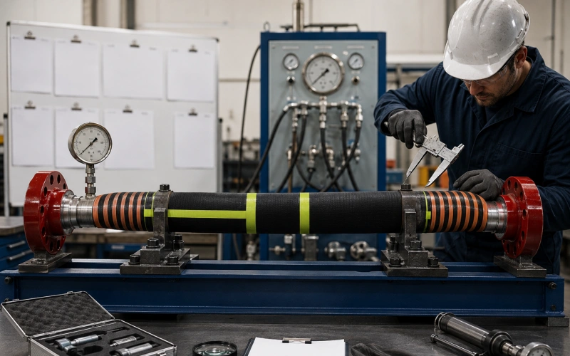
Visual inspection, internal inspection, electrical checks and pressure testing answer different questions. None proves unlimited remaining life. A pressure test is a controlled technical procedure with its own hazards; it is not a substitute for identification, routing checks or a review of service history.
Do not publish or apply one universal proof-test multiplier. Test pressure, test medium, fill and vent method, temperature, pressure ramp, hold time, instrumentation, exclusion zone and acceptance criteria must come from the procedure applicable to the exact hose assembly and service.
The procedure should also state who is authorized to test, how trapped air is controlled and what happens after a failed or interrupted test.
A hose that has leaked, lost traceability, experienced a severe overpressure or received an unauthorized repair should not be “proved safe” by an improvised field test. Isolate it and obtain a written disposition from the manufacturer or another authorized technical authority.
Emergency Response
A leak, burst, end movement or abnormal hose motion is an energy-isolation event. Follow the site emergency plan and do not approach until the system is confirmed safe. A practical sequence is:
- Stop pumping by the approved remote or protected method.
- Isolate the pressure source and prevent unintended repressurization.
- Maintain or enlarge the exclusion zone and account for personnel.
- Control stored hydraulic, pneumatic, mechanical and gravitational energy.
- Verify full depressurization at the designated safe point; do not infer zero energy from a quiet hose.
- Manage the fluid hazard, spill and exposure response under the site plan and safety data.
- Tag the hose out of service, preserve the scene where required and record the event before the system is disturbed.
Never search by touch: A high-pressure pinhole leak may be difficult to see and can penetrate skin. Do not use a hand, glove, rag or body part to locate it. Isolate and fully depressurize the system before inspection.
Documentation & Traceability
The hose tag and the job record should lead to the same assembly file. Keep enough information to reconstruct what the hose is, how it was configured, what it carried and what events may affect future use. A practical file includes:
- Data sheet and approved model/part number.
- Assembly drawing with finished length, bore, End A/End B, rigid end lengths and orientation where relevant.
- Serial number, manufacturing/assembly identification and marking details.
- Factory or service pressure-test record under the applicable approved procedure.
- Fitting, seal and material details needed to confirm the mating interface and fluid compatibility.
- Inspection, cleaning, storage, service and pressure/temperature excursion history.
- Applicable certificates, witness records or project documents specifically required for that order.
- Quarantine, repair rejection, return-to-service or disposal decision with the responsible authority.
AlienFrac can use the RFQ and order review to define the data sheet, test record, assembly drawing, fitting details, traceability and applicable certificates required for the offered assembly. Do not assume one certificate or one family-page statement covers every size, pressure, liner and end combination.
High-Pressure Frac Hose Safety FAQ
How often should a high-pressure frac hose be inspected?
Inspect before installation and before each job, monitor from outside the exclusion zone during operation, and inspect again after depressurization and cleaning as the approved procedure requires. Additional inspection intervals should reflect service severity, manufacturer guidance, site requirements and the hose history.
What pressure rating should I use for a frac hose?
Use the complete assembly’s documented maximum working pressure and make sure it covers the maximum expected operating pressure and reviewed transients. Do not use proof or burst pressure as the working rating, and do not let a lower-rated end, adapter, seal or mating component set an unsafe mismatch.
Are whip checks required on high-pressure frac hoses?
A restraint may be required, but a generic whip check is not a universal solution. Use the restraint type, rating, placement and anchor specified by the manufacturer, system designer and site risk assessment for the exact assembly and credible failure motion.
Can a damaged frac hose be repaired in the field?
Do not make an unauthorized field repair or hide damage with tape, clamps or a cover patch. Remove the assembly from service and obtain written disposition from the manufacturer or another authorized technical authority.
What is the minimum bend radius for a frac hose?
It is the smallest bend radius permitted for the selected hose under the stated installation condition. Use the value on the controlled product data or assembly drawing. Do not copy a value from a different model, size or service, and do not force the bend immediately behind the end connection.
When must a frac hose be removed from service?
Remove or quarantine it for leakage, exposed reinforcement, blisters, permanent kinks, crushing, severe abrasion, coupling movement, heat or chemical damage, unknown identity, unauthorized modification, or an unreviewed pressure/temperature excursion.
Does API 16C apply to every high-pressure frac hose?
No. API 16C is relevant when the assembly is actually specified within choke-and-kill service and the applicable qualification scope. A general high-pressure frac treatment hose needs the standards and validation basis appropriate to its own assembly and duty.
Final Pre-Start Check
Before pumping, the crew should be able to answer five questions without guessing: Is this the correct identified assembly? Are pressure, fluid and temperature within its approved envelope? Are both ends matched and fully made up? Is the route free of twist, tight bends, unsupported ends and abrasion points? Are the restraints, exclusion zone and emergency controls in place?
If any answer is unclear, stop and resolve it before pressurization. For a product-level review, send the operating envelope, route, End A/End B details and documentation list to AlienFrac. The result should be an assembly-specific decision backed by current drawings and records—not a generic promise based on the words “high pressure.”