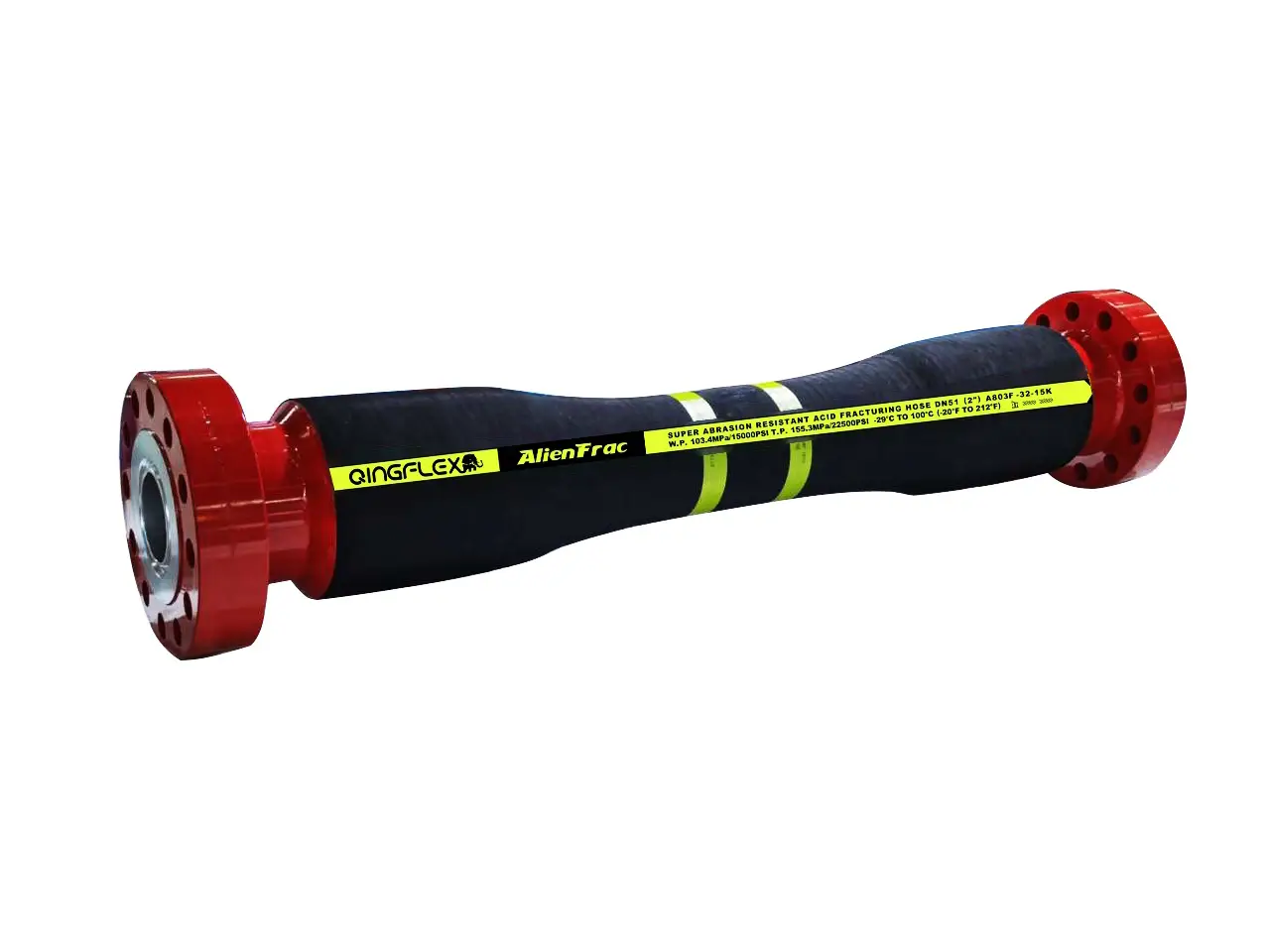
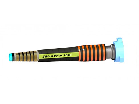
When a frac line has to carry abrasive or chemically aggressive fluid at high pressure, the hose body and its end connections need to be treated as one pressure-containing assembly. AlienFrac builds full-bore frac hose assemblies with built-in couplings for acid, sand and hydraulic fracturing duties.
Start with the actual service: fluid recipe, solids, working and surge pressure, temperature, bore, length, routing and the connection required at each end. We will use those details to narrow the construction and identify anything that still needs engineering confirmation.
Tell us what the hose will carry, how hard it will be pumped and how it will connect. AlienFrac will review the operating envelope, identify a suitable built-in frac hose path and list any information still needed before quotation.
“Built-in” describes how the end connection is incorporated into the hose assembly. The coupling is built into the assembly during manufacture instead of being added later as a standard field-style crimp. The finished hose is supplied, tested and documented as a complete unit.
That construction choice can support a robust connection zone, but the label alone is not proof of performance. The selected hose still has to match the fluid, pressure, temperature, bend, movement and connection loads. Ask for evidence that applies to the exact assembly you plan to order.
A full-bore, steel-reinforced hose for compatible water-, oil-, foam- and acid-based fracturing fluids. Built-in hammer unions and hubs suit layouts where a compact high-pressure connection is required. Select the bore, pressure class, length and end combination from the operating data—not from the connection name alone.
Choose the flange-ended assembly when the hose must connect directly to flanged pressure equipment. State the flange standard, nominal size, pressure class, sealing face, material, orientation and any swivel requirement for both ends. A flange family name by itself is not enough to release a hose for production.
These assemblies are intended for high-pressure transfer between pumps, manifolds and other pressure-system equipment in fracturing operations. Typical service may include compatible water-based, oil-based, foam and acid-based fluids, with or without proppant. Suitability depends on the complete recipe and operating envelope.
Acid fracturing lines: provide acid type, concentration, additives, exposure time and temperature.
Sand fracturing lines: provide solids loading, particle size and shape, velocity and bend layout.
Hydraulic fracturing lines: provide fluid base, additives, working pressure, surge profile and expected cycles.
Pump, manifold and wellhead connections: provide the full end specification and installed routing at both sides.
The published AlienFrac construction uses a UHMW-PE and synthetic-rubber tube to create a full-bore flow path. The liner is the first material exposed to acid, carrier fluid and proppant, so compatibility must be checked against concentration, temperature, solids and exposure time—not just a generic chemical name.
Multiple load-bearing reinforcement layers contain pressure and help the assembly tolerate movement. The correct design depends on bore, working pressure, pressure cycling and bend duty. Proof pressure and burst pressure are test or design limits; they are not operating setpoints.
The coupling, seal area and hose reinforcement are engineered as one assembly. Hammer unions, flanges and hubs can be configured to the job, but each end must be fully specified. Connection size, pressure class, material and sealing geometry all belong in the purchase description.
The synthetic-rubber cover protects the reinforcement from normal handling and outdoor exposure. Optional armor, lifting eyes, clamps and safety restraints can be reviewed for the installation. Accessories must not force the hose below its minimum bend radius or load the end fitting incorrectly.
| Built-In Frac Hose Specification | Available Options | Details to Confirm Before Quotation |
|---|---|---|
| Working Pressure | 15,000 psi and 20,000 psi configurations | Hose model, internal diameter, overall length, duty cycle, and complete assembly pressure rating |
| Hose Tube | Full-bore UHMW-PE or synthetic rubber tube | Fluid composition, solids content, operating temperature, and exposure duration |
| Operating Temperature | −29°C to +100°C for A803F; additional temperature ranges may be available for selected configurations | Exact hose data sheet, operating limits, and pressure derating requirements |
| Integrated End Connections | Built-in hammer unions, flanges, or hubs | End A and End B size, pressure class, sealing face, material, orientation, and swivel requirements |
| Optional Hose Accessories | Safety clamps, lifting eyes, safety chains, and protective armor | Installation method, lifting requirements, handling loads, and site safety requirements |
| Testing and Documentation | Test certificates supplied with the order | Required inspection reports, pressure-test records, material certificates, and complete document index |
Compare Built-in and Crimped Oilfield Hose, both constructions can be suitable when the design, manufacturing process and qualification evidence match the service.
| Decision Point | Built-In Frac Hose | Crimped Frac Hose | Buyer Check |
|---|---|---|---|
| Connection Method | End connection is incorporated during hose manufacture | End fitting is attached using a controlled crimping process | Confirm that the exact hose-and-fitting assembly has been designed, qualified, and tested for the intended service |
| Customization | Well suited to project-specific integral ends and long hose assemblies | Well suited to standardized or customized hose-and-fitting systems within the manufacturer’s qualified range | Confirm available bore sizes, hose lengths, end connections, and assembly configurations |
| Normally inspected and managed as a complete factory-manufactured assembly | Inspection, maintenance, and component replacement requirements depend on the manufacturer’s approved procedures | Follow the manufacturer’s inspection, maintenance, repair, and retirement criteria for the exact assembly | |
| Assembly Reliability | Reliability depends on the hose design, manufacturing controls, materials, testing, and service conditions | Reliability depends on correct fitting selection, crimp specifications, assembly controls, testing, and service conditions | Review qualification records, pressure-test evidence, traceability, and quality-control procedures |
| Selection Basis | Selected according to the service envelope and documented assembly performance | Selected according to the service envelope and documented assembly performance | Do not select a frac hose based on connection method alone |
List every carrier fluid, acid, additive and cleaning chemical. Add concentration, pH, proppant loading, particle size and shape, and any H2S or CO2 exposure. “Frac fluid” is not a material specification.
Give the maximum continuous working pressure, expected surges, pulsation and approximate cycle count. Keep working, proof and burst pressure separate.
State fluid and ambient temperature, including startup, cleaning and upset conditions. Ask whether the pressure rating changes at the temperature limits.
Specify the required inside diameter, overall length datum and tolerance, target flow and allowable pressure loss. Long assemblies also need a handling and support plan.
Describe both ends separately. Include connection type, nominal size, pressure class, sealing face, material, male/female orientation, swivel requirement and any interface drawing.
Provide the installed bend, movement, support points, lifting method, dragging exposure and vehicle crossings. Note whether armor, restraints or bend restrictors are required.
List the applicable standard and edition, acceptance tests, witness points, marking, traceability, drawing, certificate, packing and language requirements. Agree these items before the supplier prices the assembly.
AlienFrac’s broader oilfield-hose business reports API Q1, API 7K and API 16C credentials. Confirm which standard, edition, certificate and marking apply to the exact frac hose assembly in your order. A company-level credential should not be read as blanket approval for every product.
No. “built-in” refers to the coupling and end-connection construction used in the hose assembly. It does not mean that the hose is permanently installed inside a frac pump or another machine.
A built-in coupling is incorporated during manufacture of the hose assembly; a crimped coupling is attached through a controlled crimping process. Either construction must be selected and qualified for the actual fluid, pressure, temperature, movement and end loads.
AlienFrac publishes 15,000 psi and 20,000 psi configurations in its frac-hose range. Availability depends on bore, length, connection and service conditions, so confirm the exact assembly data sheet before ordering.
Published options range from 100 to 1,320 ft depending on the model. Longer sections reduce connection points but change handling, reel and transport requirements.
AlienFrac’s frac hose end connection range includes built-in hammer unions, flanges, and hubs.
No compliance claim should be assumed from the category name. State the required standard and edition in the RFQ, then confirm the certificate, marking and scope for the exact assembly with AlienFrac.
Send the fluid and solids, working and surge pressure, temperature, inside diameter, overall length, both end connections, routing and bend conditions, quantity, testing, documents and delivery destination.
Do not improvise a field repair on a pressure-containing frac hose. Remove a damaged assembly from service, identify the damage and ask the manufacturer for inspection, disposition and replacement guidance.
WhatsApp us