

A shale fracturing pad does not run on one universal “frac hose.” Water transfer, high-pressure treatment, acid service and abrasive discharge are separate duties. Each has its own pressure range, hose construction, routing limits and connection requirements. Treating them as interchangeable creates specification gaps before the hose reaches the field.
The practical way to select a frac hose for shale gas operations is to follow the fluid path. Start at the water source, move through storage and blending, then identify the lines that carry treatment fluid toward the manifold or wellhead. For every segment, define the fluid, flow, pressure, temperature, hose length, routing and End A/End B interfaces.
Quick Answer: A Shale Frac Site Uses More Than One Hose Type
Most shale sites need at least two clearly separated hose duties. A TPU layflat hose handles high-volume water transfer at transfer-system pressures. A reinforced high-pressure frac hose handles treatment fluid between pressure equipment. Acid or solids-bearing service adds a third selection layer: the tube, reinforcement and ends must be checked against the exact fluid recipe and operating envelope.
Do not mix the pressure classes: A TPU frac water-transfer hose is not a 15,000 psi or 20,000 psi treatment hose. Select the hose family before selecting size, construction or connection type.
Where Hoses Fit in a Shale Fracturing Site?
A useful system map starts with the main water path and then adds the project-specific branches:
- Water source, pond or compatible produced-water supply → TPU layflat transfer line → storage, tank or blender.
- Blender or pressure equipment → high-pressure pumps → reinforced high-pressure frac hose → manifold or wellhead interface.
- Acid or aggressive chemical service → application-specific acid frac hose selected from the exact chemistry, temperature, pressure and solids data.
- Abrasive lower-pressure suction or discharge → applicable suction/discharge hose selected from slurry, pressure, temperature and routing data.
- Flowback or other transfer duty → separate review of fluid composition, gas content, solids, pressure and the published capability of the proposed product.
This system view prevents one product page from being forced to answer every application. Use the AlienFrac frac hose range as the product-family hub, then move to the page that matches the actual duty.
1. Frac Water Transfer: TPU Layflat Hose
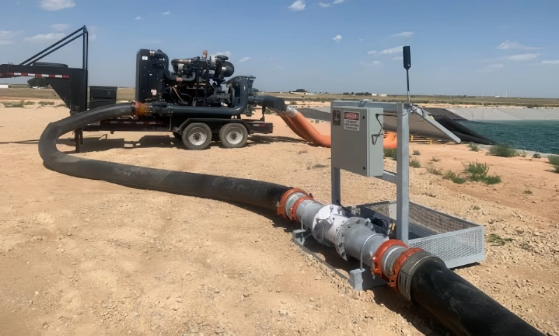
Use a TPU layflat hose for temporary or relocatable transfer of fresh water, produced water or another fluid confirmed compatible with the selected liner. The commercial advantage is not a blanket promise of lower cost or longer life. It is the ability to move a large volume through a flexible line that can be stored and deployed in long sections.
AlienFrac’s TPU frac water-transfer hose page lists TPU inner and outer liners, synthetic textile reinforcement and available lengths from 30 m to 400 m. Its published table covers multiple sizes and service-pressure options, so the exact diameter and construction must be selected from the required hydraulic duty rather than from the maximum value shown on the page.
Flow, Distance and Elevation
Required flow is only the first hydraulic input. State the total run length, elevation change, pump curve or available discharge pressure, allowable pressure loss and the number of fittings. A hose that is large enough by nominal flow may still create unacceptable friction loss over a long route. Parallel lines may be useful, but they also change connection count, manifold layout and inspection scope.
Water Chemistry and Produced-Water Compatibility
“Produced water” is not one fluid specification. Salinity, chlorides, hydrocarbons, treatment chemicals, suspended solids, pH and temperature can vary by source and over time. Provide a current fluid analysis when possible. If H2S or CO2 is present, disclose it separately; general water or chemical compatibility does not establish sour-service suitability for the complete hose assembly.
Routing and Temporary Deployment
Map road crossings, sharp stones, vehicle traffic, slope, standing water, anchoring points and access for inspection. Plan how the line will be paid out, drained, retrieved and stored. A flexible route still needs controlled bends and support at heavy couplings. If the line will move between pads, include deployment frequency and handling equipment in the RFQ. For a broader infrastructure comparison, see TPU hose vs rigid pipe.
2. High-Pressure Treatment Lines
Once fluid leaves the blender and enters the high-pressure pumping system, the selection basis changes. This section of a shale frac hose system must be treated as a pressure-containing assembly. Hose body, end fittings, adapters, seals and mating equipment all contribute to the approved limit.
AlienFrac’s high-pressure frac hose page publishes a UHMW-PE film and synthetic-rubber tube, spiral steel-wire reinforcement, abrasion- and weather-resistant synthetic-rubber cover, and a temperature range of -29°C to 121°C. It also lists hammer-union, hubbed and flanged end directions. Confirm the exact assembly because a family page does not approve every combination.
Working Pressure and Surge
State the maximum continuous working pressure and the highest expected transient, not just the pump nameplate or a round 15K/20K label. Separate working pressure from proof and burst values. Test values are not operating ratings. If the pressure class has not been fixed, review 15,000 psi vs 20,000 psi frac hose before selecting the assembly and ends.
Flow, ID and Hose Length
Define the required clear bore, flow, fluid density, solids loading and finished overall length. The end fitting can reduce the effective bore or add rigid length before the flexible section begins. Ask for the measurement datum on the assembly drawing so the hose fits the planned space without forcing a bend close to the fitting.
Pump-to-Manifold and Wellhead Connections
Specify End A and End B independently. For a hammer union, provide the exact FIG, size, pressure class, mating half and seal. For a flange, provide the applicable specification, type or class, size, bore and face/profile. For a hub, provide the exact profile, seal and connector system. The frac hose connection types guide contains a copy-ready End A/End B checklist.
3. Acid and Abrasive Frac Service
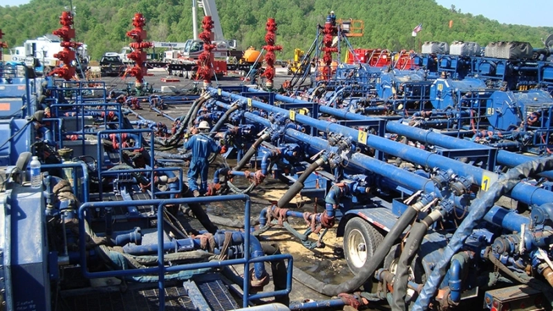
High pressure and chemical compatibility are different requirements. A hose can have the required pressure rating but an unsuitable tube or seal for the fluid. The reverse is also possible: a transfer hose may be compatible with a dilute acid yet remain unsuitable for high-pressure treatment. Both checks must pass for the complete assembly.
Fluid Composition
Provide acid type and concentration, water- or oil-based carrier, foam, inhibitors, solvents and exposure duration. Do not reduce the input to “acid frac fluid.” AlienFrac’s acid fracturing hose requirements guide explains the data needed before product selection. For the interaction between fluid chemistry, solids and wear, review abrasion and chemical resistance.
Proppant and Solids
State proppant or solid type, particle size and shape, concentration, expected velocity and whether the service is continuous or intermittent. Abrasion is affected by more than tube material; bends, local turbulence and hose movement can concentrate wear. Route the line to avoid unnecessary tight bends and include inspection access at likely wear points.
Temperature
List both fluid and ambient temperature, including startup, cleaning and upset conditions. Temperature can affect pressure capability, flexibility and chemical compatibility. Confirm any derating with the exact product data and quotation rather than carrying a family-page temperature range across every model.
4. Routing a Frac Hose System on a Shale Pad
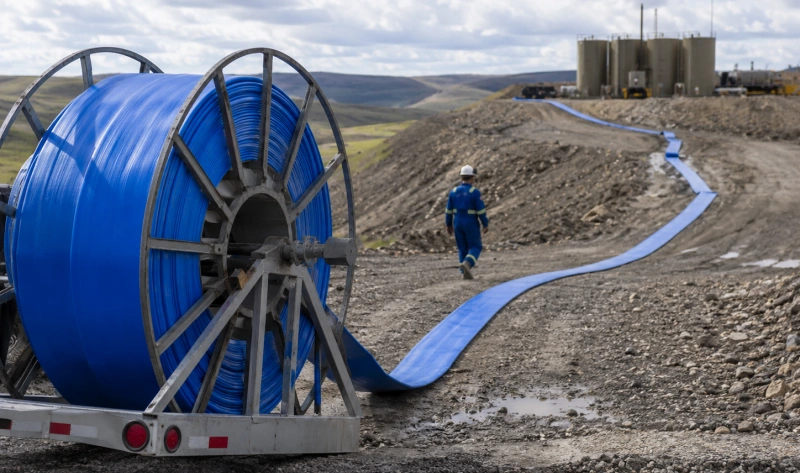
Routing belongs in the selection process, not only in the installation plan. A hose that meets fluid and pressure requirements can still be wrong for the available space. Send a layout or dimensioned sketch showing equipment locations, planned supports and the path the hose must follow.
- Keep the installed bend at or above the minimum bend radius stated for the selected hose.
- Leave a straight, supported transition at rigid end fittings; do not force the hose to bend immediately behind the connector.
- Prevent twist during make-up and operation. Confirm orientation or clocking where two rigid ends differ.
- Protect road and vehicle crossings with an approved crossing method; do not rely on the hose cover alone.
- Support heavy fittings and use approved restraints, lift eyes, clamps, armor or sleeves only where the product design permits them.
- Maintain access for pre-use checks and in-service inspection, especially at ends, bends and ground-contact points.
After use, depressurize, drain, clean as required for the fluid, inspect and store the hose under the manufacturer’s procedure. See the frac hose maintenance guide for a broader inspection and storage workflow.
5. Select End A and End B
A mixed-end assembly may be appropriate—for example, a union at one end and a flange or hub at the other—when each interface is approved. The ends do not need to match each other, but both must match their own equipment. Include the following for each end:
- Connection family and exact designation.
- Nominal size, bore and pressure rating.
- FIG number and mating half for a hammer union.
- Specification, type/class and face/profile for a flange.
- Profile, clamp or connector system and seal for a hub.
- Material, seal requirement, orientation or clocking, and mating-equipment drawing.
| Lowest-rated component rule: A 20,000 psi hose body connected through a 15,000 psi end, adapter or mating component is not a 20,000 psi assembly. Establish the working-pressure limit for the complete approved configuration. |
AlienFrac Shale-Site Hose Selection Matrix
Use this matrix to choose the next product page. It does not replace a model-level review. Public website data can change, and one connection or pressure option should not be assumed to apply to every row.
| Shale-site duty | AlienFrac product path | Published starting point | RFQ focus |
| Source or frac-water transfer | FracFlo TPU Frac Hose | TPU liners; textile reinforcement; multiple IDs, constructions and long-length options | Flow, distance, elevation, water analysis, pressure loss, route and couplings |
| Pump, manifold or wellhead treatment line | High Pressure Frac Hose | Reinforced full-bore high-pressure hose; union, flange and hub directions published | Working pressure, surge, ID, length, MBR, fluid, solids and End A/B |
| High-pressure acid or sand service | A801F Crimped Acid Frac Hose | Website shows 15K and 20K configurations, with row-specific union/flange directions | Exact chemistry, temperature, solids, part number and matching connection row |
| High-pressure acid/abrasive alternative | A801T Double-Resin Crimped Hose | Website shows 15K and 20K configurations and row-specific end directions | Exact product review; do not transfer one size’s end option to another |
| Acid suction and discharge | A811 Acid Suction and Discharge Hose | Published 500 psi models; crimped coupling, union, flange and hub options listed | Transfer duty, fluid, vacuum if applicable, temperature, route and proposed end |
| Abrasive lower-pressure discharge | A812 Abrasion Fracturing Discharge Hose | Published 400 psi discharge models and multiple end-option directions | Slurry, particles, flow velocity, temperature, routing and connection |
What Information Should Be Included in a Shale Frac Hose RFQ?
Copy the checklist below into an enquiry. Write “to be confirmed” where data are not yet available and attach the equipment layout, fluid analysis and connection drawings.
Service Role
- Water transfer / high-pressure treatment / acid treatment / abrasive discharge / other.
- Temporary, campaign-based or permanent installation.
- Quantity, required delivery date and destination.
Fluid
- Fresh water, produced water, brine, acid, oil-based fluid, foam, slurry or other.
- Complete additives/inhibitors; acid type and concentration; pH or fluid chemistry where relevant.
- Proppant/solids type, particle size and concentration; H2S and CO2 if present.
Hydraulic Data
- Required flow, total run length and elevation.
- Maximum continuous working pressure and maximum surge/transient.
- Pump data, allowable pressure loss and suction/vacuum requirement where applicable.
Hose and Connections
- Required ID/clear bore, finished overall length and measurement datum.
- Fluid and ambient temperature; minimum bend and available routing space.
- End A and End B: exact type, size, pressure class, seal, material, orientation and mating equipment.
Site and Documentation
- Road crossings, relocation frequency, anchoring/restraint, dragging exposure and inspection access.
- Assembly drawing, pressure-test certificate, marking and traceability records if required.
- Applicable standard/edition, third-party witness, packing and document-language requirements.
Common Selection Mistakes
| Mistake | Why it fails | Better specification |
| Calling every line a “frac hose” | It hides the difference between water transfer, treatment pressure and chemical duty | Name the service role and flow-path location first |
| Using a TPU transfer hose for 15K/20K pumping | Transfer-rated layflat hose is a different pressure system | Select a documented high-pressure treatment assembly |
| Writing only “produced water” or “acid” | Chemistry, solids and temperature are undefined | Attach composition, concentration, solids and exposure data |
| Selecting from pressure alone | Flow, temperature, bend radius and connections may still be wrong | Define the full operating envelope and routing |
| Copying one product row to another size | Pressure, bore, MBR or end options may change by row | Quote the exact current part number and approved drawing |
| Assuming one certificate covers every hose | Certification scope is product- and project-specific | Request the exact required document and applicable scope |
FAQ
What hose types are used on a shale gas frac site?
Typical duties include TPU layflat hose for water transfer, reinforced high-pressure hose for treatment lines, acid-service hose for defined chemical recipes, and suitable suction/discharge hose for lower-pressure slurry or transfer duties. The exact mix depends on the site flow path.
Is a TPU frac hose used for 15,000 psi pumping?
A water-transfer TPU layflat hose should not be used for 15,000 psi pumping unless the exact assembly is specifically designed, rated and documented for that pressure. AlienFrac’s published FracFlo range is a transfer-hose path, while 15K/20K products belong to the reinforced high-pressure path.
What information is needed to size a frac-water transfer hose?
Provide flow, run length, elevation, pump data, allowable pressure loss, water chemistry, temperature, route, coupling method and deployment plan. Diameter should be selected from the complete hydraulic calculation, not flow alone.
When is a high-pressure frac hose required?
Use the high-pressure product path where the flexible line forms part of the treatment-pressure system between pumps, manifolds or other pressure equipment. State working pressure, transients and the rating of every end and adapter.
How do produced-water chemistry and solids affect hose selection?
They affect tube and seal compatibility and may change abrasion risk. Provide a current analysis, temperature and solids data. Compatibility must be confirmed for the proposed hose and exposure conditions; it should not be inferred from the phrase “produced water.”
Can the same hose be used for water transfer and acid fracturing?
Do not assume so. Water transfer and acid fracturing can involve different pressures, fluid chemistry, exposure time, reinforcement and end systems. Select each duty separately unless the exact proposed assembly is approved for both.
What connections are used on high-pressure frac hose?
Depending on the product, high-pressure frac hose may use hammer unions, API flanges, hubs or mixed End A/End B arrangements. State the exact interface and pressure rating at each end and request an assembly drawing.
What data should be included in a shale frac hose RFQ?
Include service role, complete fluid and solids data, flow, working and surge pressure, temperatures, ID, length, bend/routing conditions, both connections, quantity, delivery details and required drawings, tests, markings and traceability.
Conclusion
Selecting a frac hose for shale gas operations starts with the site flow path, not a product name. Separate water transfer from high-pressure treatment, then identify any acid, solids, suction or discharge duty that needs a dedicated review.
Once the duty is clear, provide the hydraulic data, chemistry, temperature, routing and End A/End B interfaces. AlienFrac can then review the appropriate current product family and state the offered limits, connections and documents in the quotation. Send the completed RFQ checklist through AlienFrac Contact Us for a product-level review.