
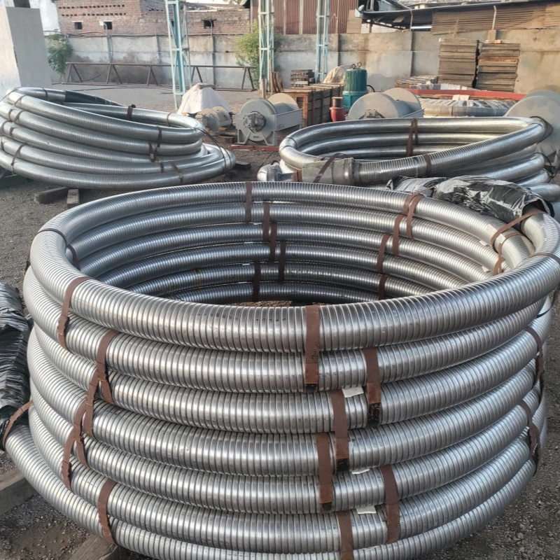
There is no single minimum bend radius for every high-pressure oilfield hose. The correct value belongs to a specific hose model, size, pressure rating, construction and operating condition. In AlienFrac’s published catalogue data, the examples on this page range from 152 mm for small-ID BOP control hose to 2,500 mm for selected flow line configurations.
That spread matters. A bend that looks generous for one assembly may be below the limit for another. Start with the exact datasheet or approved drawing, then check the real route, the rigid ends and the full movement envelope. If you are still selecting a product family, review the AlienFrac oilfield hose range and use the comparison below to narrow the options.
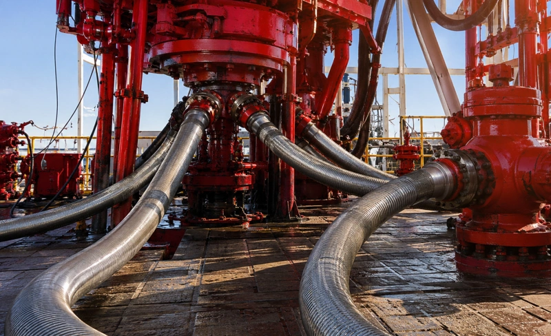
THE PRACTICAL RULE Never replace the published MBR with a universal multiplier or a familiar straight-length rule. Use the model-specific value and leave additional routing margin only when the project design, governing standard or approved engineering procedure requires it.
AlienFrac Oilfield Hose Minimum Bend Radius Comparison
The figures below summarize representative ranges published in the 2025 AlienDrill Oilfield Hose Catalogue. They are useful for early routing and product-family screening. They do not replace the current size-by-size datasheet, assembly drawing or order-specific engineering review.
| Hose family | Model | Published MBR summary | How to use it |
| API 7K cement | A802C | 1,200-1,800 mm | Single published MBR range |
| API 7K cement | A804C | Storage 1,100-1,500 mm Operation 1,200-1,600 mm | Storage and operating values differ |
| API 7K rotary / vibrator | A802D | 900-1,800 mm | Changes with size and pressure |
| API 7K rotary / vibrator | A804D | Storage 800-1,600 mm Operation 900-1,800 mm | Storage and operating values differ |
| Slim-hole rotary | A821 | 310-1,000 mm | Small-bore family; do not apply large-bore rules |
| API 16C choke and kill | A831 / A832 / A833 / A834 | About 800-2,000 mm | Depends on model, construction and configuration |
| API 16D BOP control | A841 / A842 | 152-686 mm | Small-ID control-hose range |
| API 17K flow line | A853 | Storage 900-2,300 mm Operation 1,000-2,500 mm | Largest operating MBR in this comparison |
| Fire-rated tensioner | A854 | Storage 1,400-2,000 mm Operation 1,600-2,200 mm | Movement-critical application |
| Degasser, 2,000 psi | A861 | 950 mm (3 in) 1,000 mm (4 in) | Exact values by nominal size |
Data interpretation note: Ranges combine several catalogue configurations. Use the latest approved datasheet or drawing to select one assembly. “Storage” and “operation” are not interchangeable labels.
How to Read MBR Data: Size, Pressure and Construction
Minimum bend radius, or MBR, is the tightest bend permitted for the stated hose and condition. A larger numerical radius means a gentler bend. The figure is a routing limit, not a target to force the hose against.
Read the specification in this order:
- Match the product family and model to the application: cementing, rotary drilling, choke and kill, BOP control, flow line, tensioner or degassing.
- Match the nominal inside diameter and pressure rating. Do not take a radius from a nearby size because the hose name looks the same.
- Confirm the construction, including crimped or bonded/built-in ends and any armored or unarmored option.
- Check whether the value applies to storage, operation or both.
- Confirm the manufacturer’s measurement reference and any required straight or rigid-end section on the controlled drawing.
For the broader product and standards context, see the API 7K hose range. For a focused construction comparison, see built-in vs crimped oilfield hose.
Storage MBR vs Operating MBR
Storage and operation do not always impose the same demand. A stored hose may sit in a controlled coil without pressure, flow, vibration or equipment movement. Once installed, the assembly can see pressure cycles, pulsation, axial movement, rig vibration, vessel motion, temperature change and repeated flexing. Those effects can justify a different published operating limit.
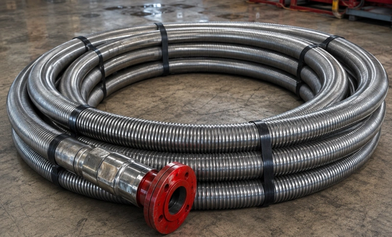
AlienFrac catalogue examples make the distinction visible:
- A804D bonded rotary/vibrator hose: storage MBR 800-1,600 mm; operating MBR 900-1,800 mm.
- A833 bonded armored choke and kill hose: storage MBR 900-1,500 mm; operating MBR 1,000-1,700 mm.
- A853 bonded flow line hose: storage MBR 900-2,300 mm; operating MBR 1,000-2,500 mm.
- A854 fire-rated tensioner hose: storage MBR 1,400-2,000 mm; operating MBR 1,600-2,200 mm.
If the datasheet lists two values, use the one that matches the actual condition. Do not install to the storage radius simply because the hose arrived coiled that way. Also plan how the hose will move from the parked position to every normal and credible transient position.
How Minimum Bend Radius Should Be Measured?
MBR is a radius, not the hose diameter and not the width of the complete U-shaped route. The measurement convention can be based on the hose centerline or another defined reference, depending on the controlled product documentation. That difference is significant on large-bore assemblies.
Before approving the route:
- Locate the MBR definition on the latest datasheet or assembly drawing.
- Confirm where the radius begins relative to the coupling, nipple, bend stiffener or other rigid section.
- Measure the installed curve using the same reference used by the manufacturer.
- Check the complete movement envelope, not only the hose position when the equipment is idle.
- Record the available radius and nearby clearances on the routing drawing.
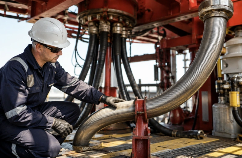
DIAGRAM NOTE Publish an MBR measurement illustration only after AlienFrac Engineering confirms the reference used in the current controlled datasheets. Label the hose OD, fitting or rigid end, bend and radius reference clearly. A polished but incorrect diagram creates more risk than no diagram.
Why Oilfield Hose MBR Changes?
MBR changes because the hose is a layered pressure-containing structure, not a simple rubber tube. Several design inputs work together; no single factor provides a dependable universal rule.
Inside Diameter and Wall Geometry
A larger bore generally needs more space to form a smooth curve, but diameter alone does not predict the final value. The A821 slim-hole rotary range and the A841/A842 BOP control range show why small-ID products must be separated from large-bore drilling, cementing and flow-line assemblies.
Pressure Rating and Reinforcement
Wire or cable reinforcement carries pressure load and controls how the hose responds to bending. Changes in reinforcement angle, layer count, material, wall thickness and pressure rating can change the allowable radius. Higher pressure does not automatically mean a larger MBR in every comparison; check like-for-like configurations.
Crimped, Bonded and Built-In Construction
The hose body and end connection are designed as one assembly. Crimped and bonded/built-in constructions can have different geometry, rigid-end behavior and published limits. Construction should be selected for the service, not treated as a price-only option.
Armor, Covers and Accessories
External armor, fire layers, bend stiffeners, guards, lifting eyes and safety clamps affect weight, clearance, support and local stiffness. Armor can protect the cover, but it does not cancel the underlying hose MBR. Make every accessory visible on the route drawing.
Temperature, Media and Movement
Temperature and media compatibility can affect flexibility and service life, while dynamic movement adds fatigue demand. Confirm the complete service envelope. Use the separate guides for oilfield hose temperature ratings, inner tube materials and sour-service oilfield hose instead of turning one MBR value into a general compatibility approval.
Bending Near Couplings and Rigid End Sections
A sharp bend beside the coupling can load the fitting, concentrate stress and distort the hose before the flexible body has room to form a smooth curve. The correct control is model- and drawing-specific. A universal “keep 18 inches straight” rule is not reliable across small BOP control hose, large cement hose and long bonded flow-line assemblies.
Review four items together: the coupling or nipple length, any specified straight section, the permitted start of bend, and the forces created by equipment movement. Support the hose so its own weight does not pull the first flexible section across an edge or lever against the connection. If the ends require clocking, show their orientation on the drawing before manufacture.
Static vs Dynamic Routing on Drilling and Well-Control Equipment
A route is static only when the connected equipment, hose and supports remain essentially fixed in service. Many drilling and well-control installations are not truly static. Rotary and vibrator hose can move with rig equipment; choke and kill lines can see pressure pulsation and platform motion; tensioner and flow-line hoses can cycle through a defined envelope.
For a dynamic route, plot the hose at both travel limits and at intermediate positions. Check for:
- a bend radius below the operating MBR anywhere in the cycle;
- torsion caused by misaligned or incorrectly clocked ends;
- tension, compression or side load at a coupling;
- contact with structures, guards, cables or adjacent hoses;
- insufficient length to absorb heave, vibration or equipment travel;
- excess length that forms a loop, snag point or uncontrolled impact zone; and
- supports or clamps that create a new hard point as the hose moves.
A clear routing drawing should show anchor points, supports, obstacles, travel directions and the available radius. Photos help, but dimensions make the review repeatable.
What Happens When a Hose Is Bent Below Its MBR?
An over-tight bend can flatten or kink the bore, disturb reinforcement geometry and concentrate cyclic strain. It may also increase pressure loss, accelerate cover wear, load the coupling or push the hose into nearby steelwork. Some damage is obvious; some develops inside the structure and is harder to see.
Stop and inspect the route if you find a kink, localized flattening, a sharp change in curvature, broken or displaced armor, cover cracking, exposed reinforcement, rubbing, a shifted fitting, leakage or unexpected hose movement. Do not straighten a damaged high-pressure hose and return it to service based on appearance alone. Follow the approved isolation, inspection and disposition procedure.
For more detail on damage mechanisms, read oilfield hose failure modes and prevention. For field checks, use the oilfield hose inspection checklist and the API hose inspection and hydrotest schedule.
Oilfield Hose Routing Checklist
Use this checklist during layout review and again after installation:
- Exact hose model, nominal ID, pressure rating and construction match the approved specification.
- The latest datasheet or drawing identifies the applicable storage and/or operating MBR.
- Available bend radius is measured from the same reference used in the controlled document.
- Every operating position stays at or above the applicable MBR.
- The bend begins beyond the specified rigid end or straight section.
- End A and End B are aligned; the assembly is not twisted during installation.
- Length is sufficient for movement but does not create an uncontrolled loop or snag point.
- Supports carry weight without pinching the hose or creating a hard bending point.
- The cover or armor cannot rub against steelwork, cables, walkways or another hose.
- Heat sources, chemical exposure, dropped objects and vehicle or personnel traffic are controlled.
- Couplings are not carrying unintended bending, axial or side load.
- The final route is documented with dimensions and clear inspection access.
What to Send AlienFrac for an MBR / Routing Review?
A useful review starts with the actual route, not only a request for “a flexible hose.” Send the following information with the RFQ:
| RFQ field | Information to provide |
| Hose | model or product family; nominal ID; required overall length and measurement datum |
| Application | equipment position and hose function |
| Pressure | normal working pressure, maximum pressure, surge and pulsation |
| Media | fluid, solids, chemistry and any sour-service conditions |
| Temperature | fluid and ambient minimum, maximum and upset conditions |
| Movement | static, intermittent or continuous; travel, vibration and heave |
| Route | available bend radius, clearances, supports, contact points and obstacles |
| Ends | End A and End B type, size, rating, material and orientation |
| Evidence | routing drawing or marked-up photos with key dimensions |
| Compliance | required standard, edition, FSL, certificate and test records |
| Commercial | quantity, destination, delivery requirement and required spares |
If certification language is part of the purchase requirement, define the exact product and document scope. The API hose certificate checklist can help procurement teams separate a standard reference, a quality-system statement and product-specific evidence.
FAQ
What is the minimum bend radius for an oilfield hose?
There is no single value for the category. Use the figure published for the exact hose model, nominal size, pressure rating, construction and condition. AlienFrac catalogue examples on this page range from 152 mm to 2,500 mm.
Is storage bend radius the same as operating bend radius?
Not always. Several bonded products in the catalogue publish separate values, with the operating MBR larger than the storage MBR in the listed configurations. Select the value that matches the hose condition.
Does a higher pressure rating always require a larger MBR?
No universal rule should be assumed. Pressure rating interacts with hose size, reinforcement, wall geometry, construction and application. Compare exact configurations on the controlled datasheet.
Can I use 1.2 times the datasheet MBR as a universal safety factor?
No. A fixed multiplier is not a substitute for the manufacturer’s value or a project-specific engineering basis. The route may need additional margin, but that margin should come from the applicable standard, risk assessment, movement analysis or approved procedure.
How close can the hose bend to the coupling?
Use the straight-section, rigid-end and bend-start requirements on the model drawing. Do not apply one distance, such as 18 inches, to every oilfield hose.
Can I measure the radius from the inside of the hose bend?
Only if that is the reference defined by the manufacturer. Many specifications use a centerline or another stated reference. Confirm the current AlienFrac drawing before measuring or creating a route template.
What information is needed to confirm a hose route?
Provide the model, ID, length, pressure, media, temperature, end connections, available radius, equipment movement, supports and a dimensioned route drawing or photos. Include the required standard and documentation scope.
Send Your Hose Model & Routing for MBR Review
Send AlienFrac your hose model or product family, routing dimensions, operating conditions and end-connection details before the assembly is quoted. The team can then compare the available route with the applicable minimum bend radius and identify any information still needed for selection. Request a hose routing review.
FINAL CHECK: The current approved datasheet, drawing and order documents control the hose selection. Catalogue ranges and this article are screening tools; they do not override project requirements or constitute installation approval.