
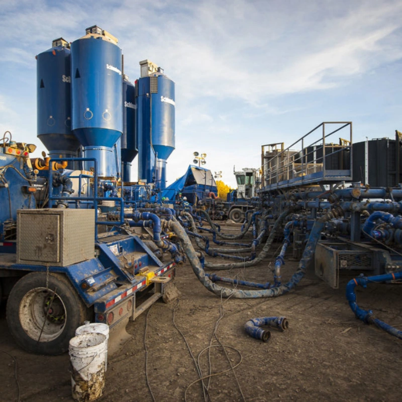
Oilfield hose failure is not limited to a burst or a visible leak. It may begin with a polished patch on the cover, a shifted coupling, a permanent kink, a soft blister, an exposed reinforcement wire, or a change in the hose’s shape under pressure. These warning signs matter because the damage you can see on the outside may be only one part of the problem.
This guide helps you identify common oilfield hose failure modes, connect each symptom to likely causes, choose a safe immediate response, and prevent the same damage from returning. It applies as a diagnostic framework—not as a replacement for the hose manufacturer’s instructions, the site hose-management plan, or the requirements for a specific API hose family.
Stop-work rule: If a high-pressure hose is leaking, bulging, kinked, exposing reinforcement, moving at the coupling, or behaving differently under pressure, depressurize and isolate the line using the approved site procedure. Keep personnel clear and place the assembly in quarantine until a qualified person and, when required, the manufacturer assess it.
Key Takeaways
- Start with the symptom, but do not assume the visible damage tells the whole story. Internal erosion, bond loss and reinforcement damage may not be obvious from the cover.
- Treat the hose as a complete assembly. The liner, reinforcement, bonding system, cover, armor, coupling, end connection and installation all affect failure behavior.
- A permanent kink, a growing bulge, reinforcement exposure, coupling movement or leakage is a reason to remove the hose from active service pending qualified assessment.
- Do not use a generic “extra pressure percentage” as a selection rule. Match the complete assembly to the defined working pressure, transients, temperature, media, movement and applicable specification.
- Prevent repeat failures by preserving evidence, identifying the mechanism and correcting the system condition—not by replacing the hose and returning it to the same routing.
Common Oilfield Hose Failure Modes
The fastest field diagnosis starts with a disciplined comparison: what changed, where it changed, and what loads act at that location? The table below is a screening tool. Final disposition must follow the applicable manufacturer, operator and project requirements.
| Visible warning sign | Likely mechanism | Immediate action | Prevent a repeat |
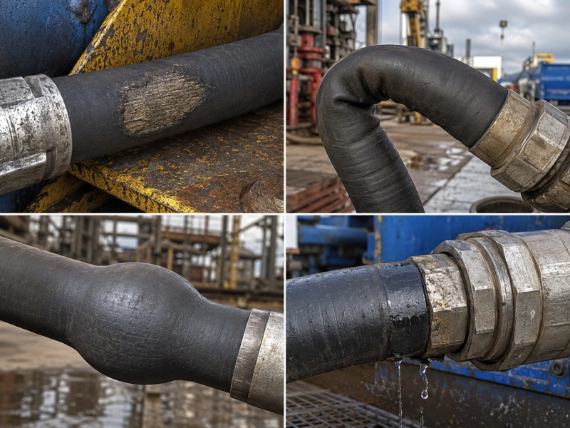
| Cover scuffing, flat spot or worn patch | External abrasion from contact, dragging, clamps or hose-to-hose rubbing | Isolate if reinforcement is visible or damage is deep; document the contact point | Reroute, support and guard the exact contact zone |
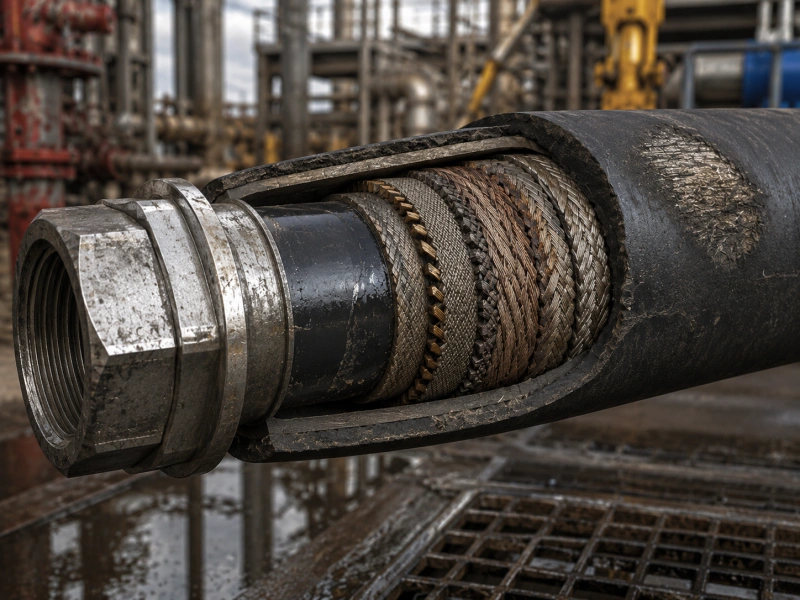
| Visible, broken or corroded wire | Cover breach and reinforcement damage | Remove from service pending manufacturer/qualified assessment | Stop abrasion and chemical exposure; protect during transport |
| Permanent kink, flattened bend or oval section | Overbend, crushing or structural distortion | Remove from service; do not straighten and return to pressure service | Use correct length, supports and minimum bend radius |
| Spiral layline or hose body rotates | Torsional loading from misaligned ends or installation twist | Depressurize; check orientation, clamps and end alignment | Install without twist and allow intended movement |
| Bulge, blister, soft spot or local diameter change | Possible liner, bond or reinforcement damage; trapped permeated gas may be involved in some services | Stop use and quarantine; record whether it changes with pressure | Verify pressure/media/temperature envelope and decompression duty |
| Reduced flow, liner fragments or unusual pressure loss | Inner-tube erosion, washout, delamination or collapse | Stop and inspect internally using an approved method | Control velocity/turbulence and select a compatible, erosion-resistant liner |
| Swelling, softening, hardening or cracking | Chemical or thermal degradation | Isolate and verify the actual fluid and temperature history | Confirm complete fluid composition, cleaning chemicals and temperatures |
| Wetness, rust stain or seepage near end | Coupling, seal, interface or end-fitting damage | Depressurize immediately and quarantine | Reduce side load; verify assembly, support and end specification |
| Coupling shift, exposed stem or changed insertion mark | End-fitting movement or loss of retention | Remove from service immediately | Control axial/side loads and monitor reference marks where specified |
| No obvious cover damage, but repeated leaks or short life | Pressure-cycle fatigue, motion fatigue, internal damage or system transients | Preserve the failed assembly and operating records for root-cause review | Review pressure history, pulsation, routing, motion and support together |
1. External Abrasion and Cover Wear
Abrasion usually appears where the hose touches a structure, a sharp edge, a clamp, the deck, or another hose. A smooth or polished patch indicates repeated rubbing; a gouge points to a more concentrated contact. Armor can also wear if it is dragged or forced against adjacent equipment.
The cover is not only cosmetic. Once wear reaches the reinforcement, moisture and chemicals can enter, wires can corrode or break, and the assembly can lose structural capacity. If reinforcement is visible, do not cover the area with tape and continue service. Record the location, isolate the assembly, and obtain the required technical disposition.
To prevent recurrence, correct the contact condition. Increase clearance, add approved supports or abrasion protection, and verify the hose can still move as intended. A sleeve helps only when it does not hide damage or create a new pinch point.
2. Exposed or Corroded Reinforcement
Exposed wire, broken strands, rust staining or a lifted reinforcement layer indicates that the load-carrying structure may be affected. The initiating cause may be abrasion, impact, cutting, chemical attack, a failed cover repair, or long-term environmental exposure.
Do not judge remaining capacity by counting a few visible wires. The extent of internal damage cannot be confirmed from the surface alone. Quarantine the hose, protect the failed area from further handling damage, and preserve photographs and identification marks for review.
3. Kinking, Crushing and Minimum Bend Radius Violations
A kink is a permanent local distortion, often with flattening on the inside of a bend and stretching on the outside. It can occur when a hose is pulled around a corner, lifted incorrectly, stored in too small a coil, or forced into a route shorter than the assembly can accommodate.
Bending tighter than the stated minimum bend radius can redistribute reinforcement, damage the liner and concentrate stress. The correct limit depends on the specific assembly and how it is installed. Use the manufacturer’s data and the minimum bend radius for high-pressure oilfield hose guide instead of applying a rule of thumb.
A permanently kinked high-pressure assembly should not be manually straightened and returned to service. Correct the hose length, connection geometry, travel envelope and supports before installing the replacement.
4. Torsional Damage and Hose Twist
A flexible hose is designed to bend, not to work as a torsion shaft. Twist can be introduced when one end is rotated during connection, when end fittings are clocked incorrectly, or when clamps force the hose to follow a helical path. The printed layline, longitudinal stripe or other orientation mark may spiral when torsion is present.
Under pressure and movement, torsion adds stress to the reinforcement and end connections. Depressurize before correcting alignment. Never use the hose body as leverage to tighten a connection. Where the system moves, confirm that supports guide the intended motion without locking the hose into twist.
5. Bulging, Blistering and Local Deformation
A bulge, blister, soft spot or unexplained local change in diameter is a serious warning sign. It may indicate reinforcement damage, loss of adhesion between layers, liner degradation, fluid migration, or gas trapped within the construction. In gas service, decompression can damage some liners or elastomers, but the mechanism depends on the material, pressure, fluid composition, temperature and decompression history.
Stop using the assembly and record whether the deformation appeared suddenly, grew under pressure, or changed after depressurization. Do not puncture a blister or cut the cover to investigate in the field. The manufacturer or an authorized specialist may require controlled examination of the quarantined hose.
6. Inner-Tube Erosion, Washout and Delamination
A hose can look acceptable outside while the liner is wearing away inside. Solids, high velocity, turbulent flow, sharp changes in direction and pulsating service can accelerate erosion. Warning signs include liner fragments downstream, unusual pressure loss, reduced flow, contamination, local heating or a recurring leak with little external precursor.
Internal inspection should use a method approved for the assembly and service, such as a borescope where access and geometry allow. If erosion is confirmed, review the flow path and operating duty as well as the liner. The oilfield hose inner-tube materials guide explains why material selection must be matched to both the media and the wear mechanism.
7. Chemical Degradation, Swelling and Softening
Chemical attack does not always look like corrosion. A polymer liner or cover may swell, soften, harden, crack, lose strength, or separate from adjacent layers. The primary process fluid is only part of the compatibility check. Water content, solids, H₂S or CO₂, acids, solvents, additives, cleaning chemicals and flush fluids can all change the exposure.
When damage appears, collect the actual fluid composition and operating history rather than relying on a generic media name such as “mud,” “oil,” or “chemical.” For H₂S-containing service, use the Sour-Service Oilfield Hose guide to define the service envelope and documentation boundaries.
8. Thermal Degradation
Heat can come from the conveyed fluid, the ambient environment, radiant equipment, steam cleaning, fire exposure or a nearby exhaust. Depending on the construction, excessive temperature may harden or crack the cover, soften the liner, accelerate chemical ageing, weaken bonds, or reduce pressure capability.
A temperature rating is not a universal property of “rubber hose.” It belongs to a specific construction, media and duty. Check continuous and transient temperatures, cold start-up conditions and external heat sources. See the oilfield hose temperature rating and fluid compatibility guide for the detailed selection workflow.
9. Coupling Movement and End-Fitting Damage
The end area often sees combined pressure load, bending, vibration, handling impact and connection stress. Warning signs include coupling movement, a changed insertion or reference mark, cracked cover near the ferrule, leakage, corrosion, damaged threads or seal faces, and a hose that bends sharply immediately behind the fitting.
Any coupling shift or leakage requires immediate isolation. Tightening an external connection may stop a joint leak, but it does not prove the hose-to-coupling interface is sound. Check end alignment, support, side load, connection specification and assembly records. For well-control applications, the API 16C hose end-connection guide provides more detail.
10. Fatigue From Pressure Cycling and Movement
Fatigue accumulates when an assembly repeatedly flexes, pulses or moves under pressure. Damage often develops at high-stress locations: near end fittings, at a clamp edge, at the tightest bend, or where the hose changes from supported to unsupported. The cover may remain normal until internal damage is advanced.
If several hoses fail in the same location or after similar service time, investigate the system. Review pressure traces, valve events, pump pulsation, motion, vibration, routing, supports, temperature, media and maintenance history. Replacing the hose without changing the load path usually recreates the same failure.
How to Diagnose Hose Damage by Visible Symptoms?
A useful diagnosis separates observation from conclusion. “The hose failed from overpressure” is a conclusion; “a 90 mm bulge appeared 300 mm behind End A after a valve-closure event” is an observation that can be tested. Use the following sequence before evidence is lost:
- Make the area safe. Depressurize, isolate, drain or decontaminate, and apply the site’s lockout and hazard-control procedure.
- Preserve the assembly. Do not cut, puncture, straighten, clean aggressively or discard the damaged area before technical review.
- Record identity. Photograph the full hose, layline, serial or asset number, end markings, orientation and connection points.
- Map the damage. Measure its distance from a defined end, length, width and relation to clamps, bends, supports and heat sources.
- Capture operating history. Include fluid composition, actual temperature, normal and maximum pressure, unusual events, movement, cleaning and storage history.
- Compare similar assets. Check whether the damage is isolated or repeating at the same system location.
- Assign disposition through the approved process. The decision may be scrap, manufacturer evaluation, controlled repair where explicitly permitted, testing, or a documented return to service.
For a field-ready list of inspection points, use the oilfield hose inspection checklist. This article focuses on failure diagnosis; the checklist covers the broader inspection routine.
Failure Differences by Hose Family
“Oilfield hose” covers assemblies with different functions and governing requirements. A visible symptom may be similar, but the consequences, evidence and disposition process can differ by hose family.
| Hose family | Failure emphasis | Diagnosis boundary |
| API 7K drilling, rotary or cement hose where applicable | Repeated movement, pulsation, abrasion, end-area fatigue, liner wear and incorrect hanging geometry | Use the exact product scope, working pressure, FSL and manufacturer instructions. Review hose length and moving geometry. |
| API 16C flexible choke and kill line | Well-control duty, fire/external exposure where specified, sour-service media, coupling/end loads and high-consequence leakage | Use the project’s API 16C scope, FSL, media and documentation requirements. Do not transfer criteria from a general hydraulic hose. |
| API 16D control-system hose where applicable | Control-fluid compatibility, fire-resistance requirements where specified, routing and reliable control function | Confirm the exact API 16D application and system requirements; the failure consequence relates to control availability as well as leakage. |
| General industrial or hydraulic hose | Abrasion, impulse fatigue, incorrect fitting selection, heat and fluid incompatibility | Use the relevant hose/fitting manufacturer limits and system standard. Do not describe it as an API hose unless the complete assembly is within that scope. |
For a side-by-side scope overview, see API 16C vs API 7K vs API 16D hoses. Always verify the current purchased specification, project requirements and product documentation before using a standard reference as a field acceptance rule.
When an Oilfield Hose Should Be Removed From Service
The exact rejection criteria must come from the applicable manufacturer, operator and project documents. Still, several conditions justify immediate removal from active pressure service pending qualified assessment:
- Leakage through the hose body or at the hose-to-coupling interface.
- A bulge, blister, soft spot or growing local change in diameter.
- A permanent kink, crushed section, severe flattening or other structural distortion.
- Exposed, broken, displaced or visibly corroded reinforcement.
- Coupling movement, a changed insertion/reference mark, cracked end area or damaged pressure-retaining connection.
- Heat, fire, arc, chemical or impact exposure beyond the assembly’s documented limits.
- A failed required inspection or test, or missing identity/traceability where the site procedure requires it for continued service.
- Any unexplained change in length, shape, stiffness, flow or behavior during pressurization.
Important: A cover repair, armor repair or coupling repair may be possible for some assemblies only when an authorized procedure and qualified facility permit it. A cosmetic-looking repair must never be treated as proof that pressure-containing layers are undamaged.
How to Prevent Recurring Hose Failures?
Define the service envelope before selecting the assembly
State the application, media and composition, solids, fluid and ambient temperature, normal and maximum working pressure, transient or pulsating duty, movement, minimum available bend radius, end connections, fire or armor needs, applicable specification/FSL and required documents. The oilfield hose specification guide provides a practical input list.
Route for movement, not only for static fit
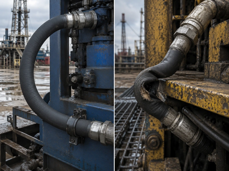
Check the hose at rest and throughout its operating travel. Keep bends away from the coupling where the assembly requires a straight section. Avoid sharp edges, pinch points, hot surfaces and support spacing that creates a hinge. Allow for pressure-related length or movement behavior stated by the manufacturer.
Install without twist or side load
Align both ends before final connection. Use the correct tools on the fittings, not the hose body. Confirm orientation marks remain straight and that clamps do not force the assembly into torsion. Support connected equipment so the hose is not used to correct pipe misalignment.
Inspect according to risk and applicable requirements
Inspection frequency should reflect the hose family, service severity, consequence of failure, manufacturer instructions, project requirements and operating history. Do not publish or adopt one universal interval for every oilfield hose. Use the API hose inspection and hydrotest schedule guide to organize the applicable documents and intervals.
Keep a traceable hose register
Record asset identity, manufacturer, assembly date where available, service location, hose family, rating, media, inspection findings, tests, repairs, unusual events and disposition. Trend repeated defects by system location and failure mode. Good records turn isolated observations into evidence for prevention.
Perform root-cause review before installing the replacement
A replacement restores the component; it does not automatically correct the cause. Before restart, ask why the damage occurred at that exact location. Correct routing, length, support, pressure transients, media compatibility, heat exposure, handling or connection load as required. Then document the change so the next inspection can verify it worked.
Related Inspection, MBR, Temperature and Hydrotest Guides
- Oilfield hose inspection checklist — Complete field inspection points and records.
- Minimum bend radius for high-pressure oilfield hose — Routing, bend limits and overbend prevention.
- Oilfield hose temperature rating — Temperature and media compatibility workflow.
- Oilfield hose inner-tube materials — Liner selection for media, wear and service conditions.
- API hose inspection and hydrotest schedule — How to organize inspection and test requirements by hose family.
- Oilfield hose product hub — AlienFrac hose families and application discussion.
Frequently Asked Questions
What are the most common oilfield hose failure modes?
Common modes include external abrasion, reinforcement exposure or corrosion, kinking, torsional damage, bulging or blistering, inner-tube erosion, chemical or thermal degradation, end-fitting damage and fatigue from repeated pressure or movement. The dominant mechanism depends on the hose family and service.
What does a bulge or blister on a high-pressure hose indicate?
It can indicate damage to the liner, bond or reinforcement, fluid migration, or gas-related layer damage in some services. Because the load-carrying structure may be affected, stop using the hose, depressurize it safely and quarantine it for qualified assessment.
Can a kinked oilfield hose be reused?
Do not straighten a permanently kinked high-pressure hose and return it to service based on appearance. A kink may disturb reinforcement and damage the liner. Remove the assembly from service and follow the manufacturer’s or approved site disposition process.
What causes reinforcement wire to become exposed?
Typical causes include repeated rubbing, dragging, cutting, impact, cover degradation or an unsuitable clamp/contact point. Exposure can also allow moisture and chemicals to attack the reinforcement. Correct the contact condition before installing a replacement.
When should an oilfield hose be removed from service?
Remove it from active service pending qualified assessment when you find leakage, a bulge, a permanent kink, exposed or broken reinforcement, coupling movement, serious end damage, or exposure beyond documented limits. Apply the exact rejection criteria for the product, manufacturer and site.
Conclusion
Effective oilfield hose failure prevention begins with a clear diagnosis. Identify the symptom, preserve the evidence, connect the damage to the loads and service history, and correct the system condition before restart. This approach is more reliable than replacing a hose based on age alone or applying one rule to every assembly.
When you need an application-specific review, send AlienFrac the hose identification, photos, damage location, media composition, pressure and temperature history, routing, movement, end connections and available inspection records. AlienFrac can use that information to discuss the appropriate hose family, documentation package and next engineering steps.