
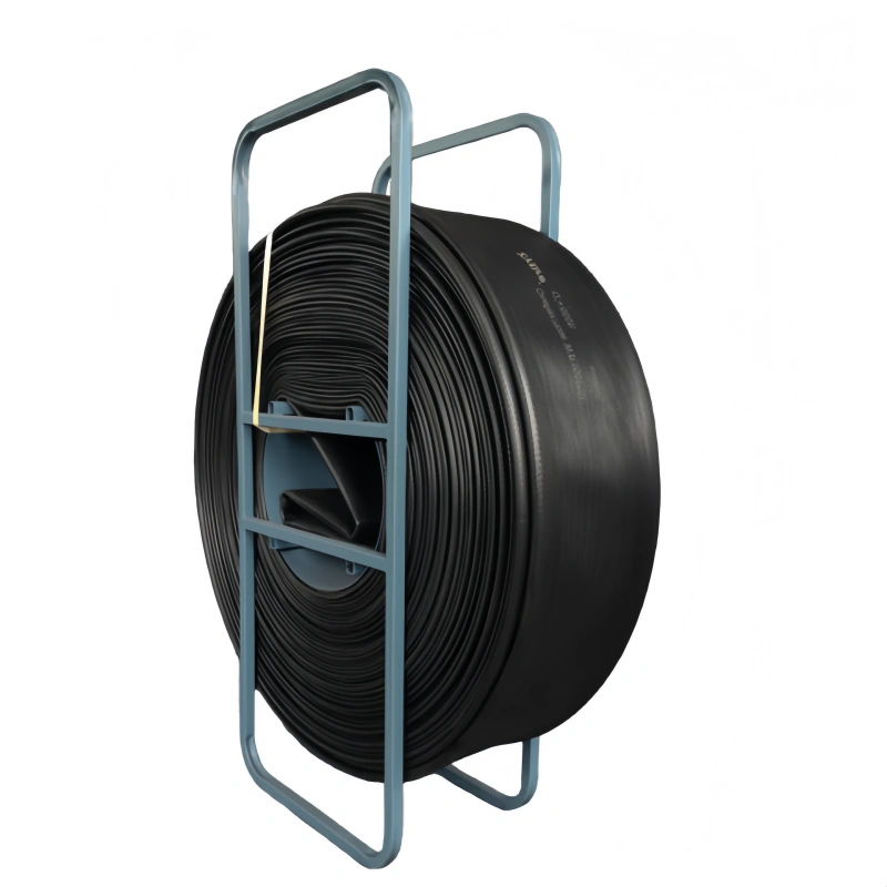
A TPU frac water transfer hose is a large-diameter layflat hose used to move fresh water, treated water, recycled water, or compatible produced water between storage, transfer equipment, and a frac site. It typically combines a TPU inner tube and outer cover with a high-tenacity woven textile reinforcement so long hose sections can carry high flow while remaining practical to deploy and retrieve.
It is not the 15,000–20,000 psi bonded or steel-reinforced hose used between high-pressure fracturing pumps, manifolds, blenders, and the wellhead. That distinction matters: a surface water-transfer line and a pressure-containing frac injection circuit have different construction, pressure classes, fittings, standards, and failure consequences.
This guide explains how a TPU frac water hose is constructed, where it sits in the water system, how to read its working-pressure range, which fluids require compatibility review, and what information you should send before requesting a quotation.
Key Takeaways
- Use TPU layflat hose for high-volume surface water transfer, not for a 15K/20K fracturing injection circuit.
- Treat published size and pressure figures as a product-family range. Not every diameter is available at every pressure.
- Select the line from flow, distance, elevation, pump curve, surge allowance, temperature, fluid chemistry, fittings, and section length—not diameter alone.
- Fresh water is the simplest duty. Treated, recycled, and produced water require a review of the complete chemical analysis and operating temperature.
- Working pressure is the operating limit for the stated conditions. Burst pressure is design-test information, not extra operating allowance.
- Couplings, gaskets, restraints, road crossings, inspection records, and proof-test documentation are part of the hose system.
What It Is—and What It Is Not?
You may see the terms fracturing TPU hose, TPU frac hose, TPU layflat hose, and frac water transfer hose used for the same broad product family. The clearest description is usually TPU frac water transfer hose because it states both the material and the job.
| Question | TPU frac water transfer hose | High-pressure frac hose |
| Primary job | Move water along the surface between source, storage, transfer pumps, and the frac location | Carry pressure-containing fracturing fluid within the high-pressure stimulation circuit |
| Typical construction | TPU tube and cover with woven textile reinforcement in a layflat structure | Bonded elastomer/thermoplastic liner with multiple steel-wire reinforcement layers and integral high-pressure ends |
| Pressure context | Product-family working pressures generally measured in hundreds of psi | Application classes can reach 15,000 or 20,000 psi |
| Handling | Long sections can be rolled, reeled, deployed, drained, and retrieved | Shorter engineered assemblies are installed in controlled high-pressure locations |
| Selection basis | Hydraulics, water chemistry, terrain, deployment plan, and connection system | System design pressure, pulsation, fluid/proppant, end connections, standards, and qualification |
If your application is on the pump discharge, manifold, blender, or wellhead side of the stimulation system, review the high-pressure frac hose range instead of selecting a layflat water-transfer hose.
How Through-the-Weave TPU Construction Works?
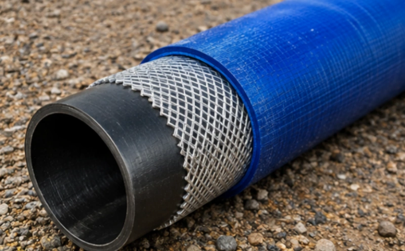
A through-the-weave hose is built as one reinforced structure. High-tenacity filament yarn is circular-woven into a jacket. TPU is then formed through and around that weave so the inner tube, reinforcement, and outer cover become mechanically integrated.
Inner TPU Tube
The inner surface contains the transferred water and provides a smooth flow path. Its exact TPU formulation, thickness, and resistance to hydrolysis, dissolved chemicals, hydrocarbons, salts, and temperature must match the duty. “TPU” is a material family, not a universal compatibility approval.
Woven Reinforcement
The circular textile jacket carries the pressure load and helps control axial elongation, diameter growth, and movement under pressure. Yarn type, weave design, coverage, and production control influence pressure capability and dimensional stability.
Outer TPU Cover
The cover protects the reinforcement from abrasion, weather, sunlight, water, and field handling. A smooth cover can simplify cleaning, while a ribbed cover can change handling and wear behavior. The available cover, color, marking, and visibility options should be confirmed for the exact model.
Through-the-weave construction reduces reliance on separate adhesive layers, but it does not make the hose immune to puncture, crushing, chemical attack, coupling damage, overpressure, or poor deployment. Construction quality still needs to be supported by dimensional checks, production controls, and hose-level testing.
Where the Hose Sits in a Frac Water System?
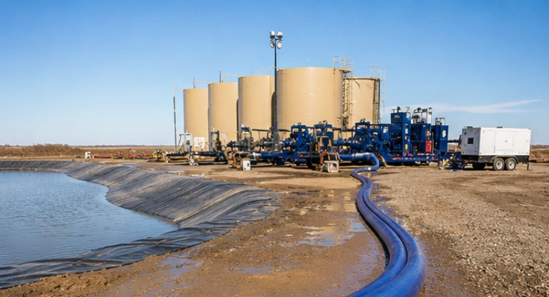
A typical surface transfer route can be read as a sequence:
- Water source or gathering point: fresh water, treated water, recycled water, or produced water enters the transfer plan.
- Storage or equalization: tanks, ponds, or other approved storage stabilize supply and demand.
- Transfer pump: the pump provides the head needed to overcome elevation, friction, fittings, and the required delivery pressure.
- TPU layflat transfer line: one or more hose runs move water across the lease road, right-of-way, or temporary corridor.
- Receiving storage or low-pressure frac-site supply: water reaches tanks, storage, treatment, or the low-pressure side of site equipment.
The exact arrangement varies by operator. The boundary remains the same: do not place a surface water-transfer hose in a pressure or fluid duty that belongs to a high-pressure stimulation assembly.
Typical Size, Working Pressure, and Length
Across AlienFrac’s currently published TPU water-transfer family, the broad range is 2–16 in. in diameter, 100–660 psi in working pressure, and approximately 100–1,320 ft (30–400 m) in section length. These numbers describe the family—not one universal hose.
| Specification | Published family range | How to use it |
| Inside diameter | 2–16 in. | Choose from required flow, acceptable velocity/head loss, pump capacity, and handling plan. |
| Working pressure | 100–660 psi | Use the exact continuous rating for the chosen diameter, construction, temperature, and fluid. |
| Section length | About 100–1,320 ft (30–400 m) | Balance fewer connections against reel capacity, route access, handling, and replacement strategy. |
| Construction | Through-the-weave TPU on the listed TPU models | Confirm tube/cover formulation, wall thickness, reinforcement, and marking on the datasheet. |
| Ends | Plain ends, grooved couplings, and project-specific options | Match pressure rating, gasket, mating hardware, restraint, corrosion environment, and installation method. |
Not every diameter is offered at every pressure. Larger-diameter products may be optimized for high flow at a lower pressure, while smaller or differently reinforced products can carry a higher working pressure. Temperature, wall thickness, weight, burst pressure, elongation, and available length can also change by model.
Use the TPU frac water supply hose overview to compare current product families, then open the FracFlo hose, FracFlo Hose Pro, or large-diameter fracturing water supply hose page for model-level data.
Working Pressure Is Not Burst Pressure
Working pressure is the maximum permitted operating pressure under the documented conditions. Burst pressure is destructive design evidence under a specified test method. It must never be treated as reserve pressure for normal operation.
The line pressure at the pump is not the only value to check. Add the effects of static elevation, friction loss through the hose and fittings, required pressure at the discharge, transient surge, valve operation, and any temperature or service derating. Then compare the calculated maximum with the rating of the weakest component in the assembled line.
Fluid Compatibility and Temperature Limits
Fresh water is usually the starting application. Treated water, recycled water, and produced water can be more demanding because their chemistry changes by basin, source, treatment program, and time. A generic statement such as “chemical resistant” is not enough for an engineering release.
Send a current water analysis and identify both routine and upset conditions. At minimum, include:
- pH, total dissolved solids, chlorides, hardness, and suspended solids;
- hydrocarbon or oil content and any known aromatic components;
- H₂S, CO₂, oxygen, and microbiological activity where relevant;
- biocides, friction reducers, scale inhibitors, corrosion inhibitors, surfactants, acids, oxidizers, and cleaning chemicals;
- minimum, normal, and maximum fluid temperature; exposure time; flush fluid; and storage condition.
Compatibility must cover the inner TPU, reinforcement exposure pathways, coupling metal, gasket or seal, and any repair material. It should also consider concentration, temperature, duration, pressure cycling, and changes after blending. If chemistry is uncertain, request a documented review or representative testing before field use.
How to Specify the Right TPU Frac Water Hose?
A useful request for quotation gives the manufacturer enough information to calculate the line and identify technical exceptions. “Twelve-inch hose, 200 psi” is not a complete specification.
| Input | What to send | Why it changes the selection |
| Flow target | Normal, minimum, and peak flow for each line | Controls diameter, velocity, friction loss, and the number of parallel lines. |
| Route | Total length, elevation profile, bends, road/ditch crossings, and access | Changes pump head, protection, section lengths, and deployment equipment. |
| Pressure | Pump curve, normal pressure, maximum pressure, surge case, and required delivery pressure | Defines the working-pressure class and system margin. |
| Fluid | Water source and full chemistry, including treatments and upset conditions | Determines compatibility of TPU, gaskets, couplings, and repair materials. |
| Temperature | Fluid and ambient minimum/maximum, continuous and short-duration | Can affect flexibility, pressure rating, chemical ageing, and handling. |
| Ends | Coupling type, size, material, pressure class, gasket, mating equipment, and restraint | The connection is part of the pressure boundary and operating system. |
| Sections | Preferred length, reel limits, connection spacing, retrieval method, and spare strategy | Balances leak points, handling, transport, repair, and replacement. |
| Documents | Datasheet, drawing, proof test, traceability, marking, inspection records, and required witness points | Makes the supplied assembly auditable and easier to manage in service. |
A Practical Hydraulic Selection Sequence
- Set the required delivery flow and pressure at the receiving point.
- Map total distance, elevation gain and loss, fittings, branches, and crossings.
- Estimate friction loss for each candidate diameter at the intended flow. Larger diameter generally reduces velocity and friction loss, but increases hose, coupling, reel, and handling requirements.
- Overlay the transfer-pump curve and identify the highest credible steady and transient pressure at every point in the route.
- Apply documented temperature, media, altitude, and service derating where required.
- Check every coupling, gasket, manifold, valve, restraint, and adapter against the same pressure and fluid envelope.
- Confirm the exact model and receive a controlled datasheet before purchase or deployment.
If the system uses several parallel lines, calculate flow distribution rather than assuming each hose receives an equal share. Differences in elevation, length, valve position, fittings, and internal condition can unbalance the lines.
TPU vs. Rubber vs. HDPE: When Each Makes Sense
No transfer medium is best for every route. The decision depends on project duration, mobility, chemistry, terrain, pressure, repair resources, and total installed cost.
| Decision factor | TPU layflat hose | Rubber layflat hose | HDPE pipe |
| Best fit | Temporary or mobile high-volume transfer where compact transport and rapid retrieval matter | Rugged transfer duties where the selected rubber compound fits the fluid and handling method | Longer-duration or fixed routes where fused pipe and civil work are acceptable |
| Deployment | Long reeled or rolled sections; flexible route changes | Flexible, but weight and packing vary by construction | Requires pipe strings, fusion or mechanical joining, alignment, and support |
| Abrasion/terrain | TPU cover is selected for wear, but crossings and sharp objects still need protection | Can be robust; actual cover compound and wall construction control performance | Good fixed-line durability; external damage and support conditions remain important |
| Connections | Long sections can reduce connection count; couplings still need rating and restraint checks | Similar system-level connection checks apply | Fused joints reduce detachable connections; branches and transitions still require design |
| When to reconsider | Permanent corridors, incompatible chemistry, unapproved road loading, or pressure beyond the model rating | Excessive handling weight, incompatible media, or poor packing/retrieval fit | Frequent relocation, limited fusion access, or urgent temporary deployment |
For a deeper commercial and operational comparison, see TPU frac hose vs. rubber hose and TPU frac hose vs. rigid pipe.
Deployment, Inspection, and Failure Prevention
Before Deployment
- Verify the hose identification, diameter, working pressure, temperature range, fluid approval, end configuration, and test status against the job plan.
- Inspect the full accessible length for cuts, punctures, deep abrasion, exposed reinforcement, blisters, soft spots, kinks, crushed areas, damaged markings, and previous unauthorized repairs.
- Inspect couplings, gaskets, clamps, restraints, valves, and adapters for wear, corrosion, deformation, contamination, and rating mismatch.
- Walk the route. Remove sharp debris where possible and plan protection at bends, ditches, roads, hot surfaces, vehicle routes, and areas of movement.
During Operation
- Lay the hose without twist, tight bends, trapped loops, unsupported drops, or contact with sharp edges.
- Fill and pressurize gradually. Vent air where the system design requires it and watch the line as pressure stabilizes.
- Keep people outside the potential release path around pressurized hose, couplings, valves, and restraints.
- Monitor pump pressure, delivery pressure, flow, visible hose movement, leaks, cover damage, and coupling condition. Investigate unexplained changes instead of increasing pump output automatically.
- Use an engineered crossing, bridge, culvert, ramp, or other approved protection. Do not assume a pressurized layflat hose can carry direct vehicle loading.
After the Job
- Isolate, depressurize, drain, and flush the line using the approved procedure before disconnecting any fitting.
- Inspect the hose again and record damage, pressure events, chemistry changes, unauthorized loading, and repairs.
- Clean and dry the hose as required for the stored fluid and climate. Retrieve it without dragging across avoidable hazards.
- Spool or roll it within the manufacturer’s bend and handling guidance, protect the ends, and store it away from heat, sunlight, standing water, chemicals, and sharp objects.
A field repair is not automatically a return-to-service approval. Stop the transfer, isolate and depressurize the line, contain the fluid, identify the damage, and follow the hose manufacturer’s approved repair and inspection procedure. Tape, improvised clamps, or an unqualified patch should not be treated as a pressure-rated repair.
What Engineering Evidence Should You Request?
A strong specification connects the hose claim to the exact product and test conditions. Ask for the documents that matter to your operator, project, and risk level:
- controlled product datasheet and assembly drawing for the selected diameter, pressure class, length, wall construction, and ends;
- working pressure, minimum burst or design-test information, temperature limits, elongation, twist, diameter change, minimum bend or handling limits, and applicable derating;
- tube, cover, reinforcement, coupling, and gasket descriptions with batch or material traceability where required;
- production hydrostatic or proof-test procedure and serialized test record for the supplied hose assembly;
- coupling installation or assembly controls, dimensional inspection, marking, serial number, and certificate of conformity;
- fluid-compatibility statement or test evidence tied to the actual water chemistry, temperature, concentration, duration, and acceptance criteria;
- installation, operation, inspection, storage, repair, and retirement instructions.
A company-level certification does not automatically certify every TPU hose model for every application. Confirm the scope, standard edition, product family, manufacturing location, and test configuration before repeating a compliance claim on a purchase order or website.
How AlienFrac Can Support the Selection?
AlienFrac publishes TPU water-transfer options across several diameter, pressure, length, and end-connection ranges. The fastest way to narrow the choice is to send the operating conditions rather than request a diameter in isolation.
Share the water analysis, target flow, total distance, elevation profile, pump curve or pressure envelope, fluid and ambient temperatures, route hazards, preferred section length, connection standard, quantity, delivery country, and required inspection documents. The technical team can then identify the closest standard construction, state exceptions, and confirm which values apply to the exact quoted hose.
When comparing manufacturers, use the TPU frac hose supplier checklist to evaluate product scope, test evidence, traceability, coupling control, and after-sales support.
Request a Project-Specific Review
Send AlienFrac your medium, flow target, distance, elevation, pump pressure, temperature, preferred diameter, end connection, section length, quantity, delivery country, and document requirements. Ask for the exact model datasheet and written operating limits with the quotation.
Conclusion
A TPU frac water transfer hose is a flexible, reinforced surface pipeline for moving large volumes of water to, from, or around a hydraulic fracturing site. Its value comes from the combination of through-the-weave TPU construction, long deployable sections, abrasion-resistant field handling, and a wide—but model-dependent—range of diameters and working pressures.
The right selection begins with the system, not the brochure. Define flow, distance, elevation, pump behavior, fluid chemistry, temperature, route, couplings, section length, inspection plan, and documentation. Then verify the exact hose rating and compatibility in a controlled datasheet and quotation.
If the application is a 15K/20K pressure-containing frac circuit, stop and specify a high-pressure frac hose system instead. Keeping those two product categories separate is the first step toward a safer, clearer, and more reliable purchase specification.
FAQ
What is a TPU frac water transfer hose?
It is a large-diameter, reinforced layflat hose used for surface transfer of fresh, treated, recycled, or compatible produced water in oilfield and shale operations. TPU forms the fluid-contact and outer surfaces, while a woven textile jacket carries pressure and controls movement.
What pressure can a TPU frac water hose handle?
AlienFrac’s published TPU water-transfer family spans approximately 100–660 psi working pressure, depending on diameter and construction. Not every size is available at every pressure. Use the rating for the exact model, fluid, temperature, ends, and operating condition.
Can it carry produced water?
It can carry compatible produced water after review. Provide the complete chemistry, treatments, temperature, solids, hydrocarbons, H₂S/CO₂ where relevant, exposure duration, and cleaning fluids. Confirm the tube, coupling, and gasket compatibility in writing.
Is a TPU layflat hose suitable for 15,000 or 20,000 psi fracturing service?
No. A surface TPU water-transfer hose is not a substitute for a bonded, steel-reinforced high-pressure frac hose used in the stimulation circuit. Use the product type and qualification required for the actual pressure-containing location.
How do I choose the diameter?
Start with required flow and delivery pressure, then calculate friction loss and velocity over the route, including elevation, fittings, branches, and the pump curve. Check handling, reel capacity, coupling size, and the number of parallel lines before fixing the diameter.
What fittings are available?
Published options include plain ends, grooved couplings, and project-specific configurations. Availability varies by model. Verify material, pressure class, gasket, mating equipment, restraint, corrosion exposure, and installation procedure for the complete connection.
Can vehicles drive over a pressurized TPU hose?
Do not assume they can. Use a route that avoids traffic or an engineered crossing/protection system approved for the vehicle load, hose size, pressure, and site conditions. Inspect the hose before and after any crossing event.
Can a damaged hose be repaired in the field?
Only with an approved procedure for the exact hose and damage. Isolate, depressurize, drain, contain the fluid, inspect the damage, and follow the manufacturer’s repair and return-to-service criteria. Improvised patches are not pressure qualification.
Does anti-static wire make every TPU hose suitable for flammable fluids?
No. An embedded conductive wire is one design feature, not a complete flammable-fluid approval. The tube, cover, coupling, seals, continuity path, grounding method, fluid compatibility, and applicable regulations must all be reviewed for the intended service.
What should be included in an RFQ?
Send flow, route length, elevation, pump and pressure data, water analysis, temperature, diameter preference, end connection, section length, quantity, delivery location, route hazards, inspection requirements, and required technical documents.