
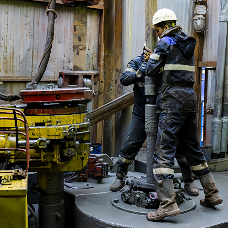
An oilfield hose for well control systems is selected by position and duty, not by a generic pressure label. A choke line carries wellbore returns toward the choke manifold. A kill line provides a controlled route for pumping fluid toward the well.
A BOP control hose transmits hydraulic power to a control function. These lines may sit close together on a rig, but they do not do the same job and should not be specified as if they were interchangeable.
This guide starts with the system position, then works through the hose family, applicable standard, pressure and temperature limits, fluid compatibility, routing, end connections, inspection records and traceability. For a wider view of drilling, cementing, frac and transfer products, use AlienFrac’s oilfield hose product range.
Key Takeaways
- Match the hose to the system position: choke, kill and BOP hydraulic control duties require different functional checks.
- Treat API 16C and API 16D as scope boundaries, not as interchangeable badges for every oilfield hose.
- Define working pressure, temperature, media, H2S conditions, ID, length, minimum bend radius, movement and end connections before requesting a quotation.
- Approve the complete assembly, including liner, reinforcement, cover or armor, fittings, seals, orientation and documentation.
- Do not assign a universal service life. Inspection findings, operating history, pressure events, exposure and manufacturer criteria should drive continued-service decisions.
Where Flexible Hoses Fit in a Well Control System?
A well control system is an arrangement of pressure-containment, flow-control and hydraulic-control equipment. Flexible hoses are used where movement, vibration, installation geometry or equipment interfaces make a rigid connection impractical. Their value is flexibility; their risk is that poor routing or an incomplete specification can load the hose in ways the pressure rating alone does not address.
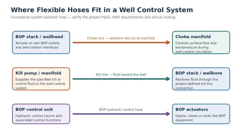
If you need a short definition before using this system-level guide, read what choke and kill lines do. The diagram below shows the three positions covered here. It is a conceptual map, not a substitute for the project P&ID, OEM manual or approved rig layout.
Choke line
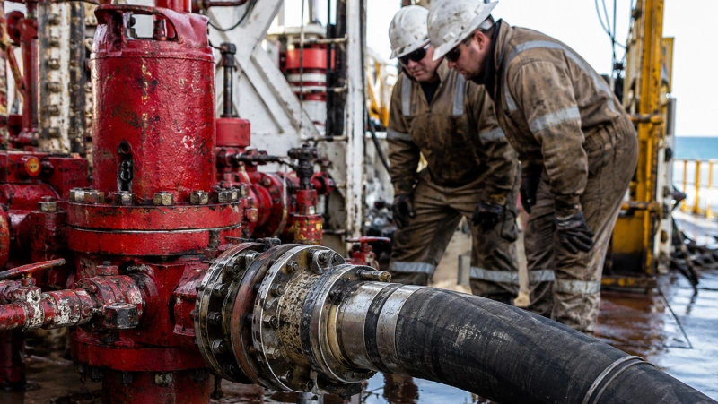
The choke line provides a controlled flow path from the well or BOP outlet to the choke manifold. During well-control circulation, it carries wellbore returns while surface equipment manages flow and backpressure.
A flexible choke-and-kill hose in this position must be evaluated for the expected pressure, bore, temperature, fluid composition, gas or multiphase duty, H2S exposure, end interfaces, movement and routing.
Kill line
The kill line provides a route for pumping the specified fluid toward the well-control equipment and wellbore. Its direction of service differs from the choke line, but a flexible assembly can belong to the same choke-and-kill hose family when the design, standard, pressure class and service envelope are appropriate.
Confirm the actual project function; do not assume that every system uses the same arrangement or media.
BOP hydraulic control line
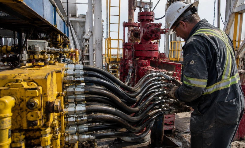
A BOP control hose carries hydraulic control fluid between the control system and the BOP functions. It is a control-power line rather than a wellbore-flow line. Selection therefore focuses on hydraulic working pressure, temperature, fire or external-protection requirements where applicable, fittings, hose routing and the response required by the control system.
Choke Line vs Kill Line vs BOP Control Hose
| System position | Primary function | Typical hose family | Selection focus |
| Choke line | Routes wellbore returns to the choke manifold for controlled circulation | Flexible choke-and-kill line / hose | WP, ID, temperature, media and H2S, ends, length, MBR, movement, documentation |
| Kill line | Pumps the project-defined kill or control fluid toward the well | Flexible choke-and-kill line / hose | WP, ID, fluid compatibility, temperature, ends, routing, test records |
| BOP control line | Transmits hydraulic power to BOP control functions | BOP hydraulic control hose | Hydraulic pressure, temperature, fire/external protection, fittings, routing, control-system requirements |
| Other interface | Connects fixed equipment where flexibility is required | Project-specific assembly | Media, pressure, motion, connection type, environment and governing specification |
Selection rule: Start with the function and system position. A pressure rating or the word “oilfield” does not make one hose suitable for all three duties.
API 16C vs API 16D: What Applies to Each Hose Position?
API’s product-program materials distinguish API 16C, Choke and Kill Equipment, from API 16D, Control Systems for Drilling Well Control Equipment and Control Systems for Diverter Equipment. That distinction is the safest way to organize this page: API 16C is the relevant starting point for flexible choke-and-kill lines, while API 16D is the relevant starting point for BOP control-system requirements.
API 7K addresses drilling and well-servicing equipment and should not be added to a well-control hose simply because the assembly is used on a drilling rig. For a focused comparison, see API 16C vs API 7K vs API 16D hoses.
| Reference | Relevant system area | Use it to confirm | Do not assume |
| API Spec 16C | Flexible choke-and-kill lines and related choke-and-kill equipment | Product scope, applicable edition, FSL or project level, design/testing/marking and required records | That every hose near the BOP is API 16C, or that one certificate covers every model and assembly |
| API Spec 16D | Control systems for drilling well-control and diverter equipment | Control-system and component requirements applicable to the selected BOP control hose | That API 16D is the governing specification for a wellbore-flow hose |
For each order, ask for the current product data sheet, applicable standard and edition, certificate or conformity statement, test record and serialized assembly identification. AlienFrac’s choke and kill hose range identifies A831–A834 constructions, while the A841 crimped armored BOP control hose is a separate control-hose product. Final applicability remains part-number and project specific.
How to Specify a Hose for Well Control Service?
A useful RFQ lets the manufacturer review an actual duty. A vague request such as “10K well-control hose” leaves too many decisions open: the same nominal pressure can cover different bore sizes, temperatures, fluids, dynamic conditions, fitting arrangements and documentation levels.
1. System position and operating duty
Name the connection points at End A and End B and state whether the assembly is a choke line, kill line, BOP hydraulic control line or another interface. Include normal operation, shut-in or emergency duty, expected flow direction, static or dynamic movement, vibration and pressure-cycle pattern.
A short P&ID excerpt and routing sketch often remove more ambiguity than several pages of generic purchasing language.
2. Pressure and test requirements
State the required maximum working pressure, normal operating pressure, expected surges or pulsation, vacuum or collapse condition if relevant, and the customer’s proof or acceptance-test requirement. Keep working pressure, factory test pressure and design-qualification or burst data separate.
Destructive burst data is not an operating limit, and a completed hydrostatic test does not prove chemical compatibility, fatigue life or suitability for a different gas duty.
3. Temperature, fluid and sour-service conditions
Provide the minimum and maximum fluid temperatures, ambient range, continuous and short-duration conditions, and any external heat or fire requirement. List the complete media rather than writing only “mud” or “hydraulic oil.” For wellbore-flow lines, include oil, water, gas, solids, brine, chlorides, inhibitors, acids or other additives that may contact the liner.
If H2S is credible, include its maximum concentration, total pressure, water phase, CO2 and other relevant chemistry. A generic “H2S resistant” claim is not a complete service envelope. The sour-service oilfield hose guide explains the material and documentation boundaries in more detail.
4. Bore, length and movement
Specify required ID or bore, finished assembly length and the dimensional reference used for that length. Confirm allowable movement, pressure-induced length change, installation tolerance and whether the hose must accommodate equipment motion. A larger bore can reduce flow restriction, but it also changes assembly weight, bend radius, fitting size, handling and support requirements.
5. Minimum bend radius and routing envelope
Provide the available routing space, the smallest installed bend and the location of supports or clamps. The manufacturer’s documented minimum bend radius is a limit, not a target. Leave margin for movement, installation tolerance and the stiff transition near end fittings.
6. End connections and orientation
Define End A and End B separately: flange, hub, hammer union, thread or another interface; nominal size; pressure class; material; seal; face or figure; and any required adapter. Provide the angular orientation of bent fittings and the dimensional reference for the finished length. The hose assembly and mating equipment should have compatible pressure ratings and sealing geometry.
For choke-and-kill assemblies, use the detailed API 16C hose end-connection checklist before the drawing is released.
7. External protection and installation environment
Describe abrasion, impact, salt spray, UV, oil, chemicals, temperature, handling damage and fire exposure. Armor can protect the cover in a harsh route, but it adds weight and can conceal damage. An unarmored hose may be easier to inspect and handle in a protected route. The choice should follow the real installation, not a general belief that the heaviest construction is always the safest.
8. Documentation and acceptance package
Agree the document package before production. At minimum, request an approved data sheet and assembly drawing, part number and serial number, material and fitting records where specified, manufacturing and coupling records, pressure-test certificate and chart, dimensional and visual inspection, marking details, certificate of conformity, and installation/inspection instructions.
Add third-party witness, NDE, sour-service evidence or a project data book only where the purchase specification requires it.
System Position → Hose Type → AlienFrac Product Mapping
The table below is a routing aid for technical review, not an automatic product release. Select the exact model only after pressure, media, temperature, connection, routing and documentation requirements have been confirmed.
| Position | Hose family | AlienFrac route | Confirm before quotation |
| Choke line | API 16C-scope flexible choke-and-kill assembly where applicable | A831 armored crimped; A832 unarmored crimped; A833 armored built-in; A834 unarmored built-in | WP, ID, temp, media/H2S, length, MBR, ends, armor, FSL/project requirements, records |
| Kill line | API 16C-scope flexible choke-and-kill assembly where applicable | A831–A834 family, selected by construction and installation | WP, ID, kill fluid, temp, routing, ends, testing and documentation |
| BOP hydraulic control | BOP control hose reviewed against applicable API 16D and project requirements | A841 crimped armored; A842 crimped unarmored | Control pressure, temp, fire/external protection, fittings, length, MBR, OEM and project requirements |
| Other flexible interface | Project-specific assembly | Technical review | Function, media, pressure, motion, connections, environment and governing specification |
Construction method is one input, not a quality ranking. Review built-in vs crimped oilfield hose when the project allows more than one assembly design.
Routing, Minimum Bend Radius and Installation Risks
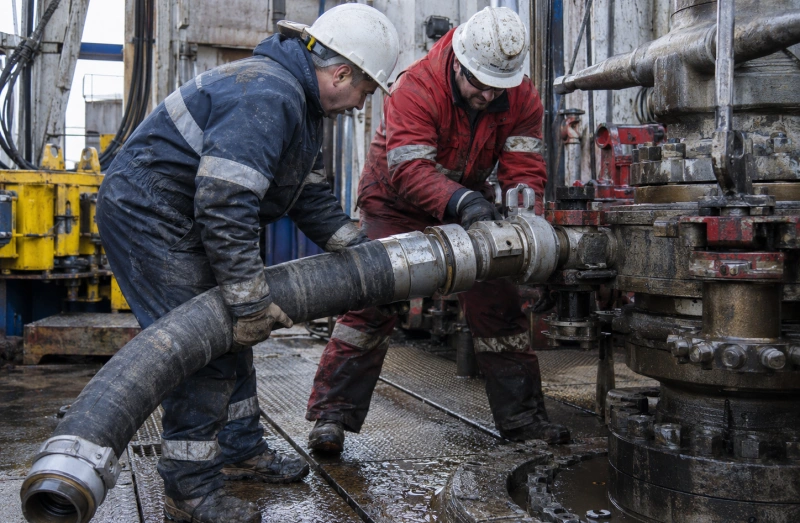
Many installation problems begin before the hose is pressurized. A correct part number can still be damaged by a short route, twist, unsupported mass or an end fitting forced into alignment. Check the installed geometry at the equipment, not only on the drawing.
- Do not bend below the documented minimum bend radius, and do not place the tightest bend directly at the coupling transition.
- Prevent torsion. Align the end connections before tightening instead of using the hose body to absorb rotation.
- Support the assembly so its weight and the weight of contained fluid do not pull on the fitting or create a tight low point.
- Keep the cover or armor clear of sharp edges, hot surfaces, moving equipment and repeated rubbing points.
- Allow for equipment movement, pressure-induced length change and installation tolerance without forcing an S-bend or kink.
- Use lifting points, clamps, bend restrictors, safety restraints and protective devices only as approved for the assembly and route.
- After installation, verify end orientation, connection engagement, clearance, support and the absence of twist before pressure is applied.
Practical check: If a hose has to be pulled, twisted or levered into place, stop and review the route, length and fitting orientation. Installation force is not a substitute for dimensional fit.
Inspection, Testing and Traceability
Inspection should follow the hose manufacturer’s instructions, the applicable standard, the equipment owner’s program, service history and project requirements. Avoid publishing a universal monthly interval or a fixed 12–24 month life: those numbers can be wrong for both severe and lightly used service.
Before use and at the defined inspection points, check the hose body, cover or armor, couplings, seals, restraints, supports, routing, marking and evidence of leakage, abrasion, corrosion, crushing, kinking, blistering, exposed reinforcement, heat or chemical attack. AlienFrac’s oilfield hose inspection checklist provides a separate field-oriented review.
A production hydrostatic test is an important pressure-integrity check for the serialized assembly under the recorded test conditions. It does not replace design qualification, gas testing, sour-fluid compatibility, impulse or fatigue evidence, fire testing, fitting-retention evidence or field inspection.
Specify the test medium, pressure, hold time, acceptance criteria, chart, gauge calibration and witness requirements before production.
Traceability closes the gap between the drawing and the hose in service. The hose marking and certificate should connect the serial number to the model, size, working pressure, date of manufacture, assembly drawing, materials or fitting records as required, production test and release status.
The operator should then retain installation date, location, service, inspections, pressure events, cleaning, storage and retirement decision.
What to Send AlienFrac for Technical Review or RFQ?
Send the following information in one package. If a field is unknown, mark it as unknown rather than filling it with a typical value; the open item can then be resolved during technical review.
- System position and function: choke line, kill line, BOP control line or other interface
- End A and End B equipment, connection type, size, pressure class, material and orientation
- Normal and maximum working pressure, surges or pulsation, vacuum if relevant, and acceptance-test requirement
- Minimum and maximum fluid and ambient temperatures, including short-duration upset or fire requirement
- Complete media and phase, including solids, water, H2S/CO2 and chemicals where applicable
- Required ID or bore, finished length, dimensional reference and allowable movement
- Routing sketch or P&ID, smallest installed bend, supports, clamps and available envelope
- External exposure: abrasion, impact, salt, UV, oil, chemicals, heat and fire
- Applicable standard and edition, project specification, FSL or other level, third-party witness and document package
- Quantity, required delivery date, destination and any packing or preservation requirements
RFQ CTA: Send your well-control system position, pressure, temperature, media, hose length, routing and end-connection data. AlienFrac can review the appropriate hose family and documentation before quotation.
FAQ
Can the same flexible hose be used for both the choke and kill line?
Sometimes the same choke-and-kill hose family can be configured for either position, but the assembly is not approved by family name alone. Confirm each line’s working pressure, flow direction, media, temperature, H2S conditions, ID, end connections, routing, movement and documentation. The final release should identify the actual position and serialized assembly.
Is a BOP control hose an API 16C hose?
Not by default. API 16C applies to choke-and-kill equipment, including flexible choke-and-kill lines. BOP hydraulic control belongs to the control-system context addressed by API 16D. Review the specific product, project specification and OEM requirements instead of treating the standards as interchangeable.
What is the most important number on a well-control hose data sheet?
There is no single number that releases the hose for service. Working pressure is essential, but the decision also depends on temperature, bore, media, gas or sour conditions, length, minimum bend radius, movement, end connections, external protection and documentation. A correct working-pressure label cannot compensate for an incompatible liner or a route below minimum bend radius.
Does a hydrostatic test prove that the hose is safe for H2S service?
No. A hydrostatic test confirms pressure integrity under the recorded liquid-test conditions. It does not by itself qualify the liner, seals or fittings for an H2S-containing environment, prove rapid gas decompression resistance, establish fatigue life or validate the complete fluid mixture.
How often should a well-control hose be replaced?
Use the manufacturer’s retirement criteria, applicable standard, owner program, inspection findings and service history. Exposure, pressure events, movement, routing, storage and damage can make a calendar-only replacement rule either too long or unnecessarily short. Remove the hose from service when rejection criteria are met or when its identity and suitability cannot be verified.
Select the Hose by System Position, Then Verify the Assembly
Selecting an oilfield hose for well control systems begins with a simple question: where does the hose sit, and what must pass through it? From there, confirm the applicable standard, working pressure, temperature, media, H2S conditions, ID, length, minimum bend radius, routing, end connections, external protection and documentation.
That sequence keeps choke, kill and BOP control duties separate while giving engineering and procurement a common RFQ language.
AlienFrac can review choke-and-kill hose constructions and BOP control hose options against the data supplied for the project. Final selection, certification statements and test requirements should be tied to the exact part number, order and approved documents—not to a general product-family claim.