
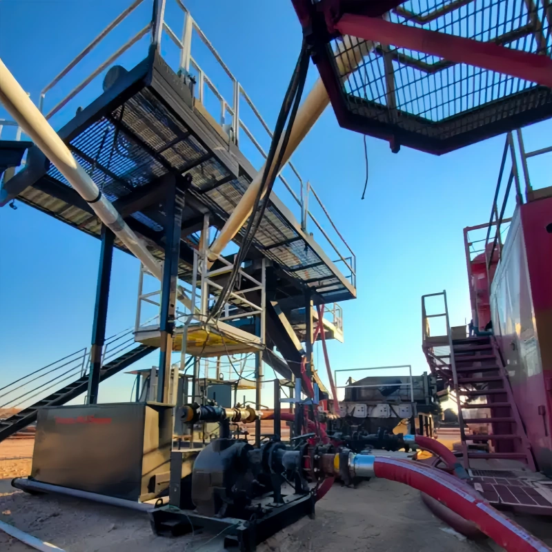
A drilling mud circulation system is a closed flow path: mud leaves the active tank, passes through the pump and high-pressure delivery line, travels down the drill string, returns through the annulus, and moves across surface-control equipment before it is reused. The flexible connections along that path do not all perform the same job.
The pump-to-standpipe connection has to handle pressure pulsation and vibration. The standpipe-to-top-drive or swivel connection must carry high-pressure drilling fluid while the rig moves. Return, transfer and degassing connections work under a different service envelope. Calling every one of these assemblies a “mud hose” hides the engineering differences that matter.
This guide maps the main hose positions in a drilling mud system, explains what each connection does, and shows which operating data should be confirmed before a hose is selected or quoted.
Key Takeaways
- Start with the hose location. A vibrator hose and a rotary drilling hose may both carry drilling mud, but they see different movement and loading.
- API 7K is relevant to the high-pressure rotary and vibrator side when the selected assembly is designed and supplied for that service. It should not be applied automatically to every return, transfer or degasser connection.
- Working pressure, temperature, fluid, inside diameter, overall length, minimum bend radius, movement and end connections must be reviewed together.
- Route the assembly so it stays above its minimum bend radius in storage and operation, without torsion, rubbing or concentrated loading near the fittings.
- For gas-cut mud, the degassing stage sits on the surface-return side. A degasser hose connects equipment in that stage; it is not a substitute for a rotary or vibrator hose.
- Send the actual rig layout, hose tag, end-connection details and required documents with the RFQ. A familiar product name is not enough to release an assembly for service.
What Is a Drilling Mud Circulation System?
A drilling mud circulation system moves conditioned drilling fluid through the well and back to the surface. The mud pump draws fluid from the active system and sends it through the standpipe and rotary connection into the drill string. The fluid exits at the bit, carries cuttings up the annulus, and returns through the flowline.
Surface equipment then removes cuttings and, where needed, entrained gas before the mud returns to the tank.
That short description is enough context for hose selection. The important question is not how every shaker, desander or centrifuge works. It is where a flexible connection sits in the flow path, what fluid it carries, what pressure and temperature it sees, and how it must move.
Drilling Mud Flow Path and Hose Locations
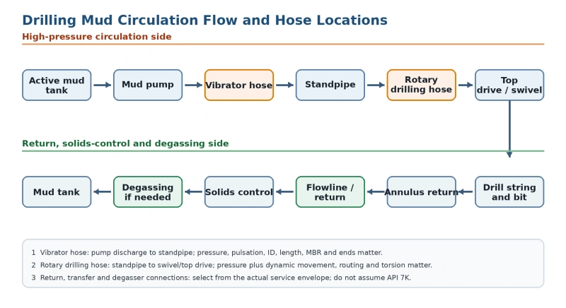
The orange section is the high-pressure circulation side. The green section is the return, solids-control and optional degassing side. The pressure class and governing requirements can change sharply between those sections, so the hose decision must follow the service location.
Hose Locations at a Glance
| Hose or connection | System position | Main role | Engineering checks |
| Vibrator hose | Mud pump discharge to standpipe | Carries high-pressure drilling mud while accommodating pulsation, vibration and small alignment changes | Service; WP; surge/pulsation; ID; length; MBR; ends; restraint |
| Rotary drilling hose | Standpipe to swivel or top drive | Carries high-pressure drilling mud through a moving connection | WP; temperature; ID; dynamic travel; length; MBR; torsion; ends |
| Flowline or transfer connection | Surface return or transfer point | Moves returning or conditioned mud between defined equipment points | Fluid; solids; flow; pressure/vacuum; temperature; abrasion; support; ends |
| Degasser hose | Degassing section on the surface-return side | Provides a flexible connection around equipment used to handle gas-cut mud | Process position; ID; WP/vacuum; temperature; MBR; routing; connection |
Important: A location name does not establish the rating. Confirm the pressure boundary, fluid, temperature, movement and required standard for the exact assembly.
Mud Pump to Standpipe: Why a Vibrator Hose Is Used
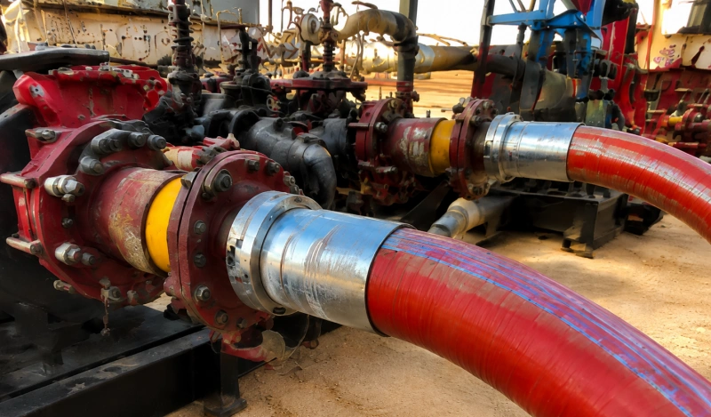
A reciprocating mud pump does not produce perfectly steady discharge. The connection between the pump discharge manifold and the standpipe can experience vibration, pressure pulsation and minor movement between pieces of equipment. A vibrator hose provides the flexible high-pressure link at this point.
The assembly still has to be treated as a pressure component. Flexibility does not correct an undersized bore, an incompatible connection or a route that forces the hose below its minimum bend radius. Before selection, confirm the normal working pressure, credible surge conditions, mud composition, fluid temperature, required inside diameter, installed length, end orientation and available support.
Do not make the vibrator line longer simply to make installation easier. Excess length can create uncontrolled movement, abrasion and poor support. Too little length can pull on the fittings and force a tight bend as equipment moves. The correct length comes from the installed geometry and the movement envelope.
For the applicable high-pressure product range and required quotation data, review AlienFrac’s API 7K hose range and rotary drilling and vibrator hose family.
Standpipe to Top Drive or Swivel: The Rotary Drilling Hose
The rotary drilling hose connects the standpipe to the swivel or top drive. Unlike a relatively short vibrator connection, this assembly must follow a larger dynamic path as the travelling equipment changes position. Pressure capability is only one part of the decision; length, bend radius, hanging geometry and movement are equally important.
Plan the route across the full travel range. Check that the hose does not twist, contact the mast or adjacent equipment, kink near an end fitting, or carry its own weight in a way the assembly was not designed to support. End connections should be oriented before final installation so the hose is not forced into torsion during make-up.
AlienFrac lists its built-in A803D rotary drilling and vibrator hose for high-pressure mud service between the standpipe and top drive or swivel, and between the pump and lower standpipe. The current product page shows 2- to 6-inch IDs, Grade D 5,000 psi and Grade E 7,500 psi options, and model-specific storage and operating bend radii.
Those published values are useful for screening, but the exact part number and live datasheet should control the order.
See the A803D built-in rotary drilling and vibrator hose page for model-level data, or start from the broader drilling hose selection hub when the service type is not yet fixed.
Return and Surface Transfer Connections
After the mud returns through the annulus, it enters the surface-return system. Depending on the rig layout, flexible connections may be used around the flowline, tanks or transfer equipment. These positions are not automatically equivalent to the high-pressure pump-to-standpipe or standpipe-to-top-drive side.
Select a return or transfer hose from its actual duty. Mud chemistry and entrained solids affect the liner. Flow rate and bore affect velocity and pressure loss. Suction or vacuum conditions may require collapse resistance. External routing can introduce abrasion, impact, weather exposure and unsupported weight. The connection type must match the equipment and the pressure class at that specific point.
If the term “flowline hose” is used on a drawing or RFQ, define the start point and end point. The same name can describe different pressure, vacuum and movement conditions on different rigs.
Solids Control and Degassing: Keep the Hose Role Clear
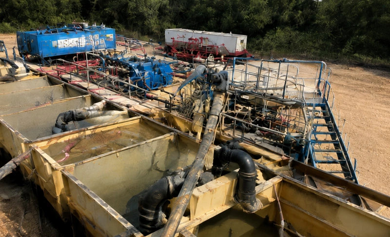
Shale shakers, hydrocyclones, mud cleaners and centrifuges condition the returning fluid. On this page, their purpose is only to show where the return stream goes. Hose selection should remain tied to the flexible connection around the equipment, not to generic performance claims about the equipment itself.
When gas becomes entrained in the returning mud, the rig may add a degassing step. Gas-cut mud can change density and flow behavior, so the process design and operating response belong to the drilling and well-control team. The hose role is narrower: connect the specified inlet, outlet or auxiliary path without becoming the weak point in the system.
Where the Degasser Hose Fits?
A degasser hose sits on the surface-return and treatment side, near equipment used to remove gas from drilling fluid. It should not be selected from the rotary-hose specification by default. The design check begins with the process position and asks whether the hose sees positive pressure, vacuum, pulsation, solids, temperature, chemical exposure or external fire-risk requirements.
AlienFrac’s A861 page currently lists 3- and 4-inch IDs, 2,000 psi working pressure, a -28 degrees C to +93 degrees C temperature range, model-specific bend radius and a 4-inch male NPT hose-tail connection description. Treat those values as product-page screening data and confirm the final assembly, connection, test basis and suitability for the actual degasser layout before purchase.
For more detail, use the mud degasser hose selection guide, check the A861 degasser hose product page, and review the system background on gas-cut mud and degassing.
Not Every Mud System Hose Is an API 7K Hose
API 7K terminology belongs where the specification and hose type make it applicable. In a drilling mud circulation system, that normally points to the high-pressure rotary drilling and vibrator connections designed for that service. It does not mean every hose handling mud anywhere on the rig is an API 7K assembly.
A return hose, tank-transfer hose or degasser connection may have a different design basis. Marking it as API 7K without checking the actual scope can create a false sense of interchangeability. Use the service location first, then identify the required standard, pressure class, FSL or project requirement for the selected model.
Certification boundary: A company certificate does not prove that every hose model carries every approval. Confirm the standard, edition, FSL and certification scope for the exact model and service.
How to Select a Hose by Service Location?
A practical review moves from the system to the assembly. Work through the fields below before choosing a product family.
- Identify the two connection points. Name the equipment at End A and End B. State whether the hose is on the pump discharge, standpipe, top-drive, return, transfer or degassing side.
- Define the fluid. List the mud type, base fluid, additives, solids, gas contamination and cleaning fluids that may contact the liner.
- Define pressure and vacuum. Provide normal working pressure, maximum credible surge, test requirements and any vacuum or collapse condition. Do not use proof or burst pressure as the operating rating.
- Define temperature. Provide fluid and ambient limits, including start-up and short upset conditions if they are part of the duty.
- Size the bore and length from the system. Confirm required ID, flow target, pressure-loss limits, installed distance, movement and end-to-end measurement method.
- Check bend radius and movement. Compare the planned route with the model-specific minimum bend radius in storage and operation. Include the full top-drive travel or equipment movement.
- Specify both ends completely. Give connection type, size, pressure class, seal face, orientation and any flange, union, hub or thread details.
- State documentation and inspection needs. List the required standard edition, FSL, material records, pressure-test report, inspection release, traceability, witness points and third-party requirements.
Routing, Minimum Bend Radius and Movement
A hose can meet the pressure requirement and still be installed incorrectly. Minimum bend radius is a geometric limit, not a preferred target. The hose needs margin above that limit across handling, installation and operation.
- Support the hose without creating a hard point or crushing the cover.
- Keep bends away from the end fitting and avoid a sharp change in curvature at the coupling.
- Align the end connections before tightening. Do not use the hose to correct flange or union misalignment.
- Prevent torsion. A rotary drilling hose should flex in its intended plane rather than twist along its axis.
- Check every operating position, not only the parked position.
- Protect the cover from rubbing, impact, hot surfaces and chemical exposure, while keeping the assembly inspectable.
For the engineering background and common routing errors, read the minimum bend radius guide for high-pressure oilfield hose.
Common Installation Problems
Most field problems do not begin with one dramatic mistake. They build from a route that is slightly too tight, a connection that is slightly misaligned, repeated cover contact, uncontrolled movement or an assembly kept in service after visible damage.
| Observed condition | Why it matters | Next action |
| Tight bend near a fitting | Concentrates strain and can damage reinforcement or the end transition | Stop and compare the route with the model-specific MBR; correct the geometry |
| Hose twists during make-up | Adds torsional loading that the assembly may not be designed to absorb | Realign and orient the ends before tightening |
| Cover abrasion or exposed reinforcement | Can allow environmental damage and indicates loss of protection | Remove from service for qualified inspection under the site procedure |
| Leak, bulge, blister, kink or fitting movement | May indicate loss of pressure-boundary integrity | Depressurize safely and follow the approved replacement/inspection process |
| Uncontrolled whipping or vibration | Loads the hose, fittings and nearby equipment | Review length, support, restraint and operating pulsation |
For a fuller failure review, see common drilling hose failure causes.
RFQ Data Checklist
Send enough information for the supplier to check the assembly against the rig, not just a product name. Include:
- Hose service location and function
- End A equipment and connection
- End B equipment and connection
- Required inside diameter
- Overall length and measurement method
- Normal and maximum working pressure
- Surge or pulsation conditions
- Vacuum or collapse requirement, if any
- Mud composition, solids and cleaning fluids
- Fluid and ambient temperature limits
- Static or dynamic duty
- Travel, offset, vibration and permitted movement
- Planned route and available bend radius
- End type, size, pressure class and orientation
- Required standard, edition, FSL and certification scope
- Pressure-test, inspection, traceability and documentation requirements
- Quantity, delivery location and requested date
- Rig drawing, hose tag, photos or previous assembly data
Send a practical RFQ: A marked-up layout drawing and photos of both connection points often prevent more errors than a long generic description.
Related AlienFrac Engineering Resources
- API 7K Hose – Product range and quotation data for applicable rotary, vibrator, mud and cement hose service.
- Drilling Hose – Commercial hub for choosing a drilling hose by service location.
- Rotary Drilling and Vibrator Hose – Product family overview for the two high-pressure circulation positions.
- A803D Built-In Rotary Drilling and Vibrator Hose – Model-level dimensions, pressure classes and bend-radius data.
- Mud Degasser Hose Selection Guide – Detailed selection questions for the degassing connection.
- A861 Degasser Hose – Product-page screening data for AlienFrac A861.
- Gas-Cut Mud – Why degassing appears on the surface-return side.
- Drilling Hose Failure Causes – Failure modes, inspection clues and prevention topics.
- Minimum Bend Radius Guide – How bend radius affects routing and service life.
Request a Drilling Mud System Hose Review
The right starting point is the flow path. Tell AlienFrac where the hose sits, what it carries, how it moves and what each end connects to. Add the operating pressure, temperature, ID, overall length, bend-radius space and required documents. AlienFrac can then review whether the application points to a rotary drilling hose, vibrator hose, return or transfer connection, degasser hose, or another assembly.
Send the RFQ package through AlienFrac Contact Us with the rig layout, current hose tag and connection photos when available.
FAQ
What is the purpose of a drilling mud circulation system?
It moves drilling fluid from the active system through the pump and drill string, returns the fluid with cuttings through the annulus, and conditions the fluid at the surface before reuse.
Where is a vibrator hose installed?
A vibrator hose is normally installed between the mud pump discharge line and the standpipe. Its job is to carry high-pressure drilling mud while accommodating pulsation, vibration and limited movement.
Where is a rotary drilling hose installed?
A rotary drilling hose connects the standpipe to the swivel or top drive. It must carry high-pressure mud while following the movement of the travelling equipment.
Are all drilling mud hoses API 7K?
No. API 7K may apply to an appropriate rotary or vibrator hose on the high-pressure circulation side, but return, transfer and degasser hoses must be selected from their actual service and the applicable product requirements.
What information is needed to quote a mud system hose?
Provide the service location, fluid, ID, overall length, working pressure, temperature, movement, minimum bend-radius space, both end connections, required standard/FSL, documentation, quantity and delivery location.
How is a degasser hose different from a rotary hose?
A degasser hose connects equipment on the surface-return and degassing side. A rotary hose connects the standpipe to the swivel or top drive on the high-pressure circulation side. The pressure, movement, construction and governing requirements can be different.
Why does minimum bend radius matter?
Bending tighter than the model-specific limit can overstress the liner and reinforcement, especially near the fittings or during movement. Check both storage and operating limits against the full installed route.