
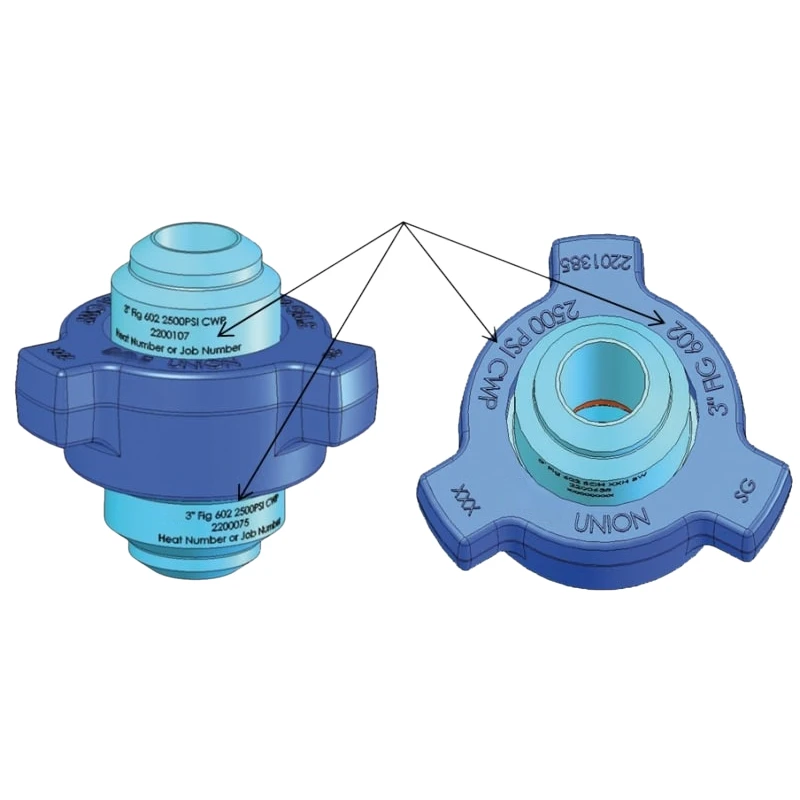
To read hammer union markings, start with the permanent marks on the wing nut, male sub, and female sub. Confirm five items: figure number, nominal size, working-pressure or service information, manufacturer identification, and heat or lot traceability.
Then compare those marks with the approved drawing, purchase order, and material or inspection records. Color is useful for screening, but it is not proof of identity.
This check matters because parts that appear to engage can still be incompatible. A complete hammer union should be positively identified before it is assembled or pressurized. If a critical mark is missing, unreadable, or inconsistent, stop and quarantine the component rather than guessing.
Key Takeaways
- Read permanent stamped, forged, cast, or otherwise durable identification before relying on paint.
- Match the figure number, nominal size, pressure or service class, and manufacturer across the mating components and controlled documents.
- Do not assume the figure number alone proves the exact pressure, material, temperature, or sour-service suitability of a particular component.
- Use the heat number, forging lot, batch, serial number, or part number to connect the physical component to its records.
- Remove any component with missing, altered, contradictory, or untraceable identification from the job until the original manufacturer or responsible engineer confirms it.
30-Second Hammer Union Marking Checklist
- Figure: Read the figure number on every relevant component. Do not accept a match based only on thread engagement or appearance.
- Size: Confirm the same nominal size on the wing nut and both subs, then compare it with the drawing and mating equipment.
- Pressure and service: Read any CWP, rated working pressure, test-pressure, standard-service, or sour-service designation. Do not confuse a factory test pressure with the permitted working pressure.
- Manufacturer and part identity: Confirm the maker’s name or mark and any part number, material reference, or serial identifier.
- Traceability: Record the heat number, forging lot, batch code, or other identifier and match it to the MTC/MTR, certificate, inspection report, and PO.
- Condition: Check that the marks are genuine and legible and that the threads, lugs, seal pocket, and sealing surfaces show no damage that could hide or invalidate identification.
Where to Find Markings on a Hammer Union?
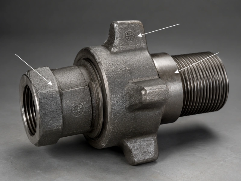
Marking locations vary by manufacturer, figure, size, and component design. Inspect the full circumference and accessible faces of the wing nut, male sub, and female sub after cleaning them. Common locations include the nut face or outer rim, the body of a sub, and the end area close to the connection. The male and female halves can also be checked visually, but component shape does not replace marking verification.
A mark may be stamped, forged, cast, engraved, or applied by another controlled permanent method. Paint bands, tags, and storage labels can help you find the right bin, but they can fade, be repainted, or move with a component. Clean only with a method approved for the material and coating; do not grind, deepen, restamp, or otherwise alter a pressure-containing part in the field.
Hammer Union Marking Decoder
| Marking field | What it normally helps identify | What to verify |
| Figure number | The connection family and interface designation. | Same figure on mating components and documents; correct geometry, seal system, and application for that manufacturer. |
| Nominal size | The named connection size, often shown in inches. | Same size across the connection; bore and dimensional interface against the controlled drawing. |
| CWP / RWP / pressure mark | The manufacturer’s stated working-pressure information for defined conditions. | Units, service class, temperature limits, size-specific exceptions, and whether the mark is working or test pressure. |
| Service/material mark | The organization responsible for the marked component. | Consistent manufacturer identification and authentic supporting documentation. |
| Service/material mark | A controlled component, drawing, or material identifier. | Revision and description in the manufacturer’s records; never decode an unfamiliar abbreviation by assumption. |
| Heat/forging lot | Traceability to raw material or forging production records. | Exact match to the MTC/MTR and any forging, heat-treatment, hardness, or inspection records. |
| Batch / serial / date code | Traceability to machining, assembly, inspection, or release records. | The supplier’s documented code format and the supplied certificate package. |
| Service / material mark | Standard or sour-service designation, material grade, or another service limitation. | Exact meaning in the manufacturer’s drawing/specification and suitability for the actual fluid, pressure, temperature, and environment. |
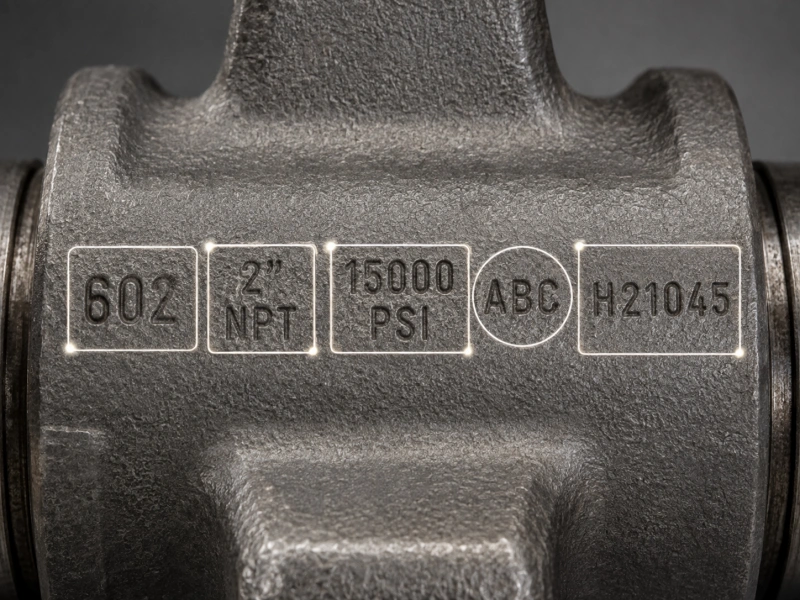
1. Figure Number: What It Tells You—and What It Does Not
The figure number is usually the first field people look for because it identifies a hammer union family. It helps you narrow the expected connection geometry, pressure class, seal arrangement, and intended service. Alienfrac publishes separate pages for products such as FIG 100, FIG 200, FIG 206, FIG 602, and FIG 1502.
The figure number is not a complete purchase specification. Pressure, available size, end connection, temperature class, standard or sour service, seal material, and test requirements can vary with the exact design and manufacturer. For example, two parts may carry familiar figure numbers yet still differ in service class or documented operating limits. Read the other markings and the controlled documents before accepting the component.
Never treat partial thread engagement as confirmation. Industry safety alerts document cases in which unlike hammer union components appeared to make up or temporarily hold pressure before failing. Identification requires matching the critical markings and records—not a trial fit.
2. Nominal Size and End-Connection Markings
Nominal size identifies the named connection size; it does not necessarily equal every measured diameter. Read the size on each component and compare it with the assembly drawing. If the component has a threaded, butt-weld, or another end preparation, verify the connection type separately because it may be controlled by a part number or drawing rather than the large figure stamp.
- Confirm the same nominal size on the wing nut, male sub, and female sub.
- Check the bore, thread form, pitch, shoulder, seal pocket, and other interface dimensions using the manufacturer’s approved inspection method when required.
- Do not assume that components are compatible because a nut starts onto a sub.
- If a gauge or dimensional inspection is required, use the specified calibrated gauge and acceptance criteria. A tape measure is not a substitute for controlled inspection.
3. Working Pressure and Test Pressure Markings
A pressure marking must be read with its label, unit, service class, size, and temperature basis. CWP commonly means cold working pressure, while a test or proof pressure describes a specified acceptance test. A higher test-pressure value is not the allowable operating pressure. Use the detailed hammer union pressure ratings and color codes guide only after the component identity is confirmed.
Before use, compare the physical mark with the manufacturer’s current data sheet and controlled drawing. Confirm that the complete assembly—including both subs, wing nut, seal system, attached hose or piping, and mating equipment—has an operating rating suitable for the maximum credible pressure and temperature. The lowest applicable rating controls the assembled pressure boundary.
4. Manufacturer, Part Number, Heat Number, and Lot Traceability
Manufacturer identification is a safety field, not just branding. Marking conventions are not identical across companies, so a code that means a heat number for one maker may be a part or material reference for another. Record the mark exactly as found, including letters, separators, and leading zeros, and ask the original manufacturer to decode any unfamiliar field.
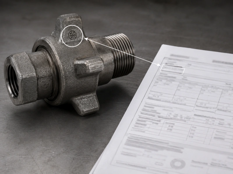
A heat number normally connects the steel to its material test record. A forging lot can connect several forged parts to a production batch. Part numbers, machining batches, serial numbers, and inspection-release numbers may provide additional links. Strong traceability lets a buyer move from the physical component to the material, heat-treatment, hardness, dimensional, NDE, pressure-test, and release records required by the order.
- Photograph the full component and a readable close-up of every marking area.
- Copy the code into the inspection record without “correcting” its format.
- Match the heat number to the MTC/MTR and the part or lot number to the supplier’s traceability index.
- Check that the document description, size, figure, material, quantity, PO, and revision identify the same supplied item.
- Escalate duplicate, missing, overwritten, or mismatched codes to QA and the original manufacturer.
5. Sour-Service and Material Identification
Do not approve a hammer union for H₂S service based on paint color or a loose “NACE” description alone. Sour-service suitability must be evaluated for a defined component and material condition in a defined environment.
The exact metallic materials, hardness, heat treatment, weld condition, seals, pressure, temperature, H₂S conditions, and applicable document requirements all matter. Review the applicable hammer union standards as part of the purchase specification.
Look for the manufacturer’s specified service marking, then verify what it means in the drawing, material specification, certificate, and purchase order. Current project language may refer to ANSI/NACE MR0175/ISO 15156 for metallic materials in H₂S-containing oil and gas production environments, but that reference is not a blanket certificate for the complete assembly or every possible sour environment.
Confirm the applicable edition and environmental limits with the responsible materials engineer.
For a product-specific example, review the FIG 2202 markings and service specification when evaluating an acid-gas application. Confirm the figure identification, pressure rating, seal arrangement, material requirements, and applicable service documentation for the exact configuration before use.
Why Color Coding Is a Secondary Check?
Color coding is fast and useful during receiving, storage, and pre-job screening. It is also vulnerable to repainting, weathering, contamination, inconsistent field practices, and manufacturer-specific conventions. That is why color should confirm an identification, not create one. Check pressure ratings and color codes only in the current manufacturer-specific documentation.
For a product-specific color reference, see the FIG 402 black-nut identification example, where the black nut and black connecting parts can support visual identification after the figure and other required markings have been verified.
- First, read the permanent figure, size, pressure/service, manufacturer, and traceability markings.
- Then compare the paint scheme with the manufacturer’s current, model-specific documentation.
- If paint and permanent marks disagree, stop. Do not repaint the part to make the visual code “match.”
- If the permanent marks cannot be positively verified, quarantine the component even if the color looks familiar.
How to Verify the Markings Against the Drawing, MTC, and PO
- Create a marking record. Photograph the complete assembly and each component, then transcribe every mark exactly.
- Check the controlled drawing. Match the figure, nominal size, end preparation, part number, seal arrangement, service class, material, revision, and dimensional interface.
- Check material traceability. Match each heat or forging-lot identifier to the MTC/MTR and any heat-treatment, hardness, impact, or NDE records required by the PO.
- Check manufacturing and acceptance records. Match batch or serial identifiers to dimensional inspection, pressure testing, coating, assembly, and final-release documentation as applicable.
- Check the purchase order and data sheet. Confirm the required standard and edition, working conditions, service classification, test scope, documentation, and approved deviations.
- Resolve every discrepancy before release. The supplier’s written, technically responsible confirmation should identify the exact component and controlled document; a verbal assurance is not enough.
Red Flags: Stop and Quarantine the Component
| Red flag | Why it matters | Required response |
| Missing or unreadable critical marks | The component cannot be positively identified. | Remove from the job and quarantine pending manufacturer/QA verification. |
| Figure or size differs between components | Parts may partially engage but form a hazardous connection. | Do not assemble or pressure-test the combination. |
| Pressure or service marks conflict | The assembly rating or service suitability is uncertain. | Use the controlled drawing and supplier records; escalate the discrepancy. |
| Paint disagrees with permanent marks | Paint may be wrong, old, or manufacturer-specific. | Trust neither by itself; verify the component from permanent ID and records. |
| Different or unknown manufacturers | Interface and marking conventions may differ. | Do not mix unless the responsible manufacturers and engineering authority explicitly approve the exact combination. |
| Heat/lot code does not match records | Material and production evidence cannot be tied to the part. | Hold the item and request corrected traceability or replacement. |
| Restamped, ground, welded, cracked, or distorted area | Identification or pressure-boundary integrity may have been altered. | Remove from service and obtain a formal engineering disposition. |
| Seal type or service designation is uncertain | The seal/material may not suit the pressure, temperature, or fluid. | Verify the exact seal and service envelope before assembly. |
Alienfrac Marking and Traceability Review
When you review Alienfrac hammer union products or contact Alienfrac, send the required figure, nominal size, end connection, maximum working pressure and temperature, standard or sour-service conditions, fluid details, and documentation package. Include the mating-component information when compatibility must be reviewed.
Before publication of a product-specific marking example, Alienfrac Engineering/QA should approve a real photo and its decoded fields against the controlled drawing and order records. The published example should show only verified markings and should state that other figures, sizes, and manufacturing revisions may use different layouts.
FAQ
What if the color and stamped figure disagree?
Stop and quarantine the component. Do not use color to overrule a permanent mark, and do not repaint it to remove the conflict. Verify the manufacturer, figure, size, pressure/service class, and traceability against the controlled drawing and records.
Can hammer union parts from different brands be mixed?
Do not assume they can. Similar appearance, a familiar figure number, or partial thread engagement does not prove compatibility. Use components from the same positively identified manufacturer and assembly unless the original manufacturers and responsible engineering authority explicitly approve the exact combination.
What should I do if a marking is faded or missing?
Remove the component from the job and quarantine it. Clean it only by an approved method and ask the original manufacturer or qualified inspection authority for positive identification. If critical identity cannot be restored from controlled records, do not use the part.
Does the figure number always equal the pressure rating?
The figure helps identify a connection family, but it is not enough by itself to release a component for service. Check the actual pressure marking and the manufacturer’s model-, size-, temperature-, and service-specific documentation. Do not infer working pressure from a test-pressure value.
Which documents should be requested with a hammer union?
The package depends on the PO, but common items include the approved drawing and data sheet, certificate of conformity, MTC/MTR, heat-treatment and hardness records, dimensional report, NDE records, pressure-test certificate, coating record, traceability index, inspection release, and sour-service material statement where applicable.
Where are hammer union markings located?
Inspect the nut face or rim and the bodies of the male and female subs. The exact location and code format vary by manufacturer and design, so inspect the full component and use the manufacturer’s drawing or identification guide.
Final Field Rule
Read the permanent markings first, verify them against controlled documents, and treat color as a secondary check. If figure, size, pressure/service, manufacturer, and traceability do not all support the same component identity, do not assemble or pressurize the union. Identification takes minutes; a mismatch can put people, equipment, and the entire operation at risk.
For product matching, documentation requirements, or a marking review, contact Alienfrac with clear photographs and the service conditions for your application.