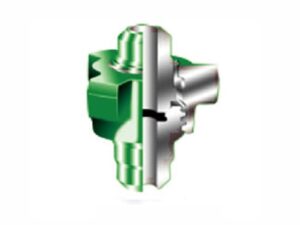
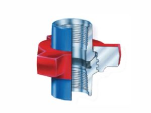
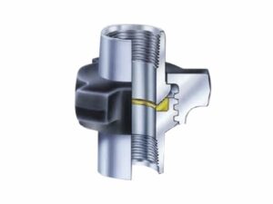
The AlienFrac FIG 200 hammer union has a compact configuration for low-pressure kill lines and medium-pressure air, water, oil, or steam service. It has a working pressure of 2,000 PSI NSCWP and a 3,000 PSI test pressure. A blue nut and gray parts provide the specified color identification, while butt weld Sch. 40 is specified for the applicable configuration. Use the dimensions and ordering checklist below to confirm the required size before requesting a quotation.
FIG 200 is intended for defined low- and medium-pressure service rather than the high-pressure applications associated with other hammer union figures. The compact construction, stated pressure limits and application range make the product data the starting point for selection. Confirm the complete system specification instead of choosing by appearance, color or nominal size alone.
Pressure and color help identify the product, but both must be checked against the figure marking and approved system data. The hammer union pressure ratings and color codes guide provides broader identification context without replacing the FIG 200 specifications listed here.
The service description does not by itself confirm media compatibility, temperature limits, mating-component suitability, or installation conditions. Provide the operating medium and service conditions with the RFQ so the requested configuration can be reviewed.
Butt weld Sch. 40 is specified for the applicable FIG 200 configuration. Confirm the required end arrangement and mating components before ordering. For general background on end styles used across the wider category, review the hammer union connection types guide; the inclusion of an end style in that guide does not indicate that it is available for the FIG 200 product.
| Nominal size (in) | Nominal size (mm) | Total length (in) | Total length (mm) | Nut radius (in) | Nut radius (mm) | Nut code as supplied | Part code as supplied | Weight (lb) | Weight (kg) |
|---|---|---|---|---|---|---|---|---|---|
| 2 | 25.4 | 2 11/18 | 68.3 | 1 15/18 | 49.2 | SF/SF | CDB/SF | 1.75 | 0.8 |
| 1 1/4 | 31.7 | 2 7/8 | 73 | 2 3/8 | 60.3 | SF | SF | 2.37 | 1.1 |
| 1 1/2 | 38.1 | 2 7/8 | 73 | 2 3/8 | 60.3 | SF | SF | 2.37 | 1.1 |
| 2 | 50.8 | 3 5/18 | 84.1 | 2 20/32 | 73.8 | SF | SF | 2.25 | 2.4 |
| 2 1/2 | 63.8 | 4 1/18 | 103.2 | 3 11/18 | 93.7 | SF | SF | 10 | 4.5 |
| 3 | 76.2 | 4 3/8 | 111.1 | 3 7/8 | 98.4 | SF | SF | 15.25 | 6.9 |
| 4 | 101.6 | 4 13/18 | 122.2 | 5 | 127 | SF | SF | 20 | 9.1 |
| 6 | 152.4 | 6 6/8 / 1/4* | 168.3 | 6 7/18 / 11/18* | 163.5 | SF | SF | 44.5 | 20.2 |
FIG 200 is identified by a blue nut and gray parts. The dimension table also lists the supplied material codes, including SF and CDB/SF, to help match quotations and product documentation. These codes should not be used to determine chemical composition, alloy grade, or standards compliance unless they are supported by separate controlled material documentation.
When replacing an existing union, record the figure number, nominal size, pressure, manufacturer marking and available heat or lot information. The field guide to reading hammer union markings explains which details to capture before requesting a match.
FIG 206 hammer union is a separate product figure with its own sealing, service, and dimensional data. Refer to the FIG 206 product page when that figure is specified; do not substitute it for FIG 200 based only on a similar pressure family or connection appearance.
FIG 207 is another related figure with its own specifications. Where a project references connector interchangeability, verify the exact component and approved configuration before purchase. See the FIG 207 hammer union specifications for detailed product data.
Include the following information with your enquiry:
FIG 200 has a rated working pressure of 2,000 PSI NSCWP.
The specified test pressure is 3,000 PSI.
FIG. 200 is listed for low-pressure kill lines and medium-pressure air, water, oil, or steam service. Final selection must also consider the complete system and operating conditions.
The specified color identification is a blue nut with gray parts. Verify the figure marking and pressure data in addition to color.
Butt weld Sch. 40 is desired for the applicable configuration. Confirm the required end arrangement before ordering.
Send the required size, connection details, service conditions, quantity, destination, and documentation needs. Contact AlienFrac for a FIG 200 hammer union quotation and product-matching review.
WhatsApp us