
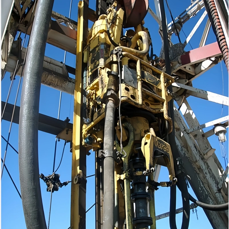
A drilling hose rarely fails for just one reason. On a working rig, pressure pulsation, movement, routing, mud abrasion, heat, and installation geometry act together. A cover scuff that looks minor may be the visible result of a hose that is too short. A leak near a coupling may begin with torsion or an unsupported rigid end, not with a defective fitting.
This guide focuses on rotary drilling hose and vibrator hose assemblies in dynamic mud-circulation service. It covers the standpipe-to-swivel or standpipe-to-top-drive connection, as well as the mud-pump-to-standpipe vibrator line. It does not repeat every generic oilfield hose failure mode.
Instead, it helps you connect field symptoms to rig-specific causes, decide what to inspect, and know when the safest action is to stop, depressurize, and quarantine the assembly.
If you are still defining the hose type, start with AlienFrac’s drilling hose selection overview. For the broader product and standard context, see the API 7K hose guide.
Key Takeaways
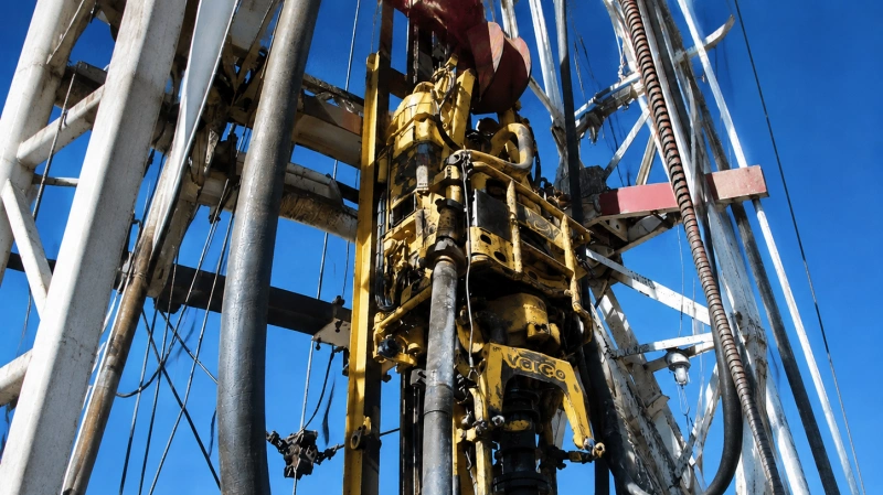
- Treat routing as part of the hose design. Length, minimum bend radius, travel, supports, and connection orientation must work together through the full operating envelope.
- Never use test pressure or burst pressure as the normal operating limit. The rated working pressure and any approved application limits control service.
- A rotary hose can be bent without being correctly installed. Multi-plane bending and torsion can damage reinforcement even when the visible curve looks smooth.
- Damage near an end fitting often points to load transfer, misalignment, insufficient straight length, or an unsupported rigid end—not simply a loose connection.
- Drilling fluid compatibility is conditional. Review the actual liner compound against mud type, solids, additives, temperature, pressure, and exposure time.
- If reinforcement is exposed, the hose leaks, a fitting moves, or the body shows bulging, kinking, severe flattening, or blistering, remove pressure and quarantine the hose for qualified review.
Quick Drilling Hose Failure Diagnosis Matrix
| Visible symptom | Likely rig-specific cause | Immediate check | Safe next action |
| Flattening, kink, or local buckle | Dynamic bend below MBR; support or travel conflict | Observe the complete travel path without pressure where permitted | Stop use if deformation remains or reinforcement damage is suspected |
| Spiral distortion or hose “corkscrewing” | Torsion or multi-plane bending | Check layline rotation and end orientation | Depressurize, correct geometry, and send damaged hose for review |
| Cover worn at one repeatable location | Contact with derrick, frame, clamp, or another hose | Identify the contact point through the motion cycle | Eliminate contact; quarantine if reinforcement is visible |
| Leak or bulge close to coupling | End-fitting stress, axial load, sharp bend, or fitting movement | Inspect rigid-end support, connection alignment, and fitting security | Remove from service; do not tighten or patch a pressurized assembly |
| Soft spot, blister, or local swelling | Liner damage, permeation, thermal exposure, or chemical incompatibility | Review media, temperature, upset history, and hose condition | Quarantine for manufacturer or qualified inspector evaluation |
| Pressure loss with no external leak | Possible liner erosion, delamination, or bore restriction | Review solids, velocity, flow trend, and internal inspection records | Stop if performance changed unexpectedly; inspect internally |
| Abrupt movement or severe vibration | Pump pulsation, inadequate restraint, wrong length, or support issue | Check anchors, dampening, routing, and operating pressure history | Correct the system cause before returning the hose to service |
Safety boundary: This matrix supports triage; it does not approve a damaged hose for continued service. Site procedures, the assembly manufacturer, and a competent inspector control the final decision.
1. Dynamic Over-Bending and Minimum Bend Radius Violations
Minimum bend radius (MBR) is not only an installation dimension. On a rotary hose, the bend changes as the top drive or swivel moves. On a vibrator line, pump vibration and pressure pulsation repeatedly flex the same zones. A route that meets MBR when the rig is idle may violate it at the top or bottom of travel, during connection, or when a support shifts.
Over-bending compresses the inside of the curve and stretches the outside. Repeated cycles can distort the tube, displace reinforcement, concentrate stress, and overload the coupling transition. Watch for flattening, a permanent set, cover cracking on the outside radius, local buckling, or a sharp bend close to the fitting.
Check the manufacturer’s operating MBR for the exact part number and size—not a generic rule of thumb. AlienFrac’s detailed minimum bend radius guide for high-pressure oilfield hose explains why routing, installed geometry, and movement must be reviewed together.
- Verify the curve at every expected equipment position, including start-up, shutdown, maintenance, and maximum travel.
- Keep the bend away from the coupling transition and support rigid ends so their weight does not force a local hinge.
- Do not pull a hose into place and assume pressure will make the route acceptable. A pressurized hose may move into a more damaging path.
2. Torsion and Multi-Plane Bending
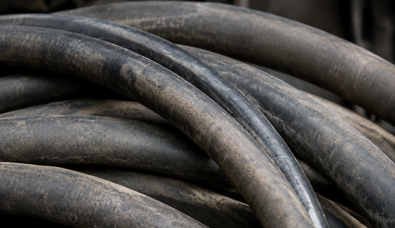
A rotary drilling hose is designed to flex, but flexing is not the same as twisting. Torsion develops when the two ends are clocked incorrectly, the hose is forced to align misoriented connections, or equipment movement rotates one end relative to the other. Multi-plane bending adds another problem: the hose is asked to curve in one direction and then immediately change plane.
The hose may still look “round,” yet its reinforcement can be carrying uneven load. The layline is a useful field reference. If it spirals around the hose after installation or changes orientation through travel, investigate before pressurizing. Also watch for fittings that pull sideways, a hose that tries to roll, and repeated movement toward nearby steelwork.
- Align connection faces before bringing the hose into position.
- Use only approved swivel or orientation solutions; never rely on the hose body to absorb connection misalignment.
- Route the main bend in one plane wherever practical, and recheck after maintenance or rig moves.
3. Incorrect Length and Axial Load
The shortest hose that reaches is not necessarily the correct hose. A hose that is too short can be placed in tension, pull on the end fittings, reduce the available bend radius, and become overloaded at maximum travel. A hose that is too long can loop, sag, rub, whip, or create a second bend plane.
Length should be defined from an agreed datum and checked against the complete route. Include the rigid end sections, connection stand-off, top-drive or swivel travel, pump movement, support points, and the space needed to maintain operating MBR. If an old assembly is being replaced, do not copy overall length alone; record where it sat, how it moved, and whether the old route showed wear.
For terminology that is often mixed in purchasing requests—including kelly hose, rotary hose, and mud hose—identify the service location first. This prevents a familiar name from hiding a different movement or pressure duty.
4. External Rubbing and Repeated Contact
External abrasion on a rotary or vibrator hose is usually a routing problem before it becomes a material problem. Typical contact points include the derrick, standpipe clamps, guard rails, cable trays, skid frames, brackets, and adjacent hoses. Motion can make the contact intermittent, so a stationary inspection may miss it.
A polished patch, missing cover texture, or a wear mark that repeats at the same position is an early warning. A sleeve can reduce surface wear, but it should not be used to conceal an unresolved contact path. If reinforcement is visible, the pressure boundary has lost external protection and the assembly should be removed from service.
- Observe the full motion envelope from a safe location and under the site’s approved procedure.
- Change routing or support geometry so the hose clears the structure; do not make a sleeve carry structural load.
- After correcting the route, inspect adjacent hoses and the opposite side of the assembly for secondary contact.
5. Coupling and End-Fitting Stress
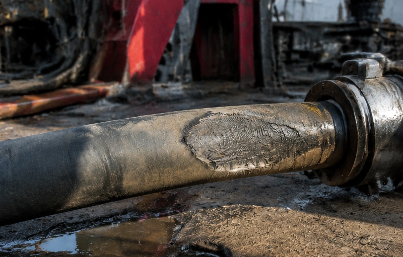
The connection zone combines flexible hose with a much stiffer end fitting. It is therefore sensitive to sharp bending, side load, axial tension, vibration, and unsupported fitting weight. Leakage near the coupling does not automatically mean the coupling was assembled incorrectly; the field geometry may be transferring repeated load into the termination.
Look for cover cracks close to the fitting, separation at the termination, corrosion, loose hardware, seal-face leakage, fitting movement, or a hose that bends immediately after the rigid section. Confirm the mating connection, pressure class, orientation, support, and installation instructions for the approved assembly.
Do not attempt a field repair, add a clamp, or tighten a connection while the line is pressurized. Depressurize, isolate, and follow the site’s lockout and verification procedure before any inspection or corrective work.
6. Mud-Pump Pulsation and Pressure Excursions
A vibrator hose is installed between the mud pump discharge and the standpipe partly because that location sees vibration and pressure pulses. The hose must still be selected for the defined service, and the system must control abnormal pressure events.
Blockages, rapid valve changes, pump start-up, equipment malfunction, and operating outside the intended envelope can create loads that normal working pressure alone does not describe.
Use the rated working pressure shown for the exact assembly and confirm how pulsation, surge, temperature, and the project specification affect selection. Do not create a fixed “20–50% safety margin” or operate from test or burst values. Proof and burst figures serve different purposes and are not substitute working ratings.
- Review pressure trends and event logs after unexplained movement, noise, leakage, or relief-system activation.
- Check that dampening, relief, anchors, supports, and instrumentation are suitable and maintained for the system.
- After a verified overpressure event, follow the defined post-event inspection and disposition process before restart.
7. Abrasive Drilling Mud and Liner Erosion
The inside of the hose can deteriorate while the cover still looks serviceable. Drilling mud may carry barite, cuttings, sand, and other solids. Velocity, solids concentration, turbulence, temperature, hose bore, and bend geometry influence where the liner wears. Local erosion can be more severe near bends or disturbed flow at the ends.
Possible field clues include an unexplained pressure or flow change, debris during flushing, abnormal vibration, a soft or bulged area, or internal findings during a qualified borescope inspection. None of these signs should be diagnosed from appearance alone. Compare them with operating history and the inspection method approved for that assembly.
- Specify mud type, solids and additives when selecting the hose—not simply “drilling fluid.”
- Keep the bore and end connections consistent with the required flow and approved design.
- Use documented internal inspection when required; an external visual check cannot confirm liner condition.
8. Temperature and Media Compatibility
Chemical compatibility is a service-envelope decision. Water-based mud, oil-based mud, synthetic-base fluid, brine, cement contamination, cleaning chemicals, hydrocarbons, and additives can affect liner compounds differently. Temperature, concentration, pressure, exposure time, and the exact compound formulation all matter.
Avoid blanket labels such as “excellent for all drilling fluids.” Provide the manufacturer with the fluid composition and maximum credible temperature, then request a written suitability review for the proposed assembly. If the fluid program changes, treat that as a change in service and review the hose again. Likewise, do not transfer a raw-material temperature limit directly to the complete hose assembly.
When to Stop Using and Quarantine a Drilling Hose?
Operators should follow the site’s approved limits and the manufacturer’s instructions. As a practical safety screen, stop, isolate, depressurize, and quarantine the assembly when any of the following is found:
- Leakage from the hose body, coupling transition, or end connection that cannot be clearly attributed to an external, non-pressure-boundary source.
- Exposed, broken, corroded, or displaced reinforcement; severe cover loss; deep cuts; or damage from impact, fire, or hot work.
- A bulge, blister, soft spot, permanent kink, flattening, collapse, or other change in hose shape.
- Fitting movement, separation, cracked termination material, damaged connection faces, or evidence of axial or side loading.
- A known overpressure, over-temperature, severe over-bend, twist, dropped-object, or chemical-exposure event outside the approved envelope.
- Missing or unreadable identification when traceability, rating, service history, or inspection status cannot be confirmed.
Do not use tape, paint, a sleeve, or a temporary clamp to return a questionable pressure hose to service. Mark the hose, record the reason for removal, prevent accidental reinstallation, and obtain a documented disposition from the responsible authority.
Post-Event Field Inspection Workflow
- Make the area safe. Stop the operation, isolate energy, depressurize, drain where required, and confirm the line is safe to approach under the site procedure.
- Preserve the evidence. Record the hose ID, layline, service location, date, pressure and temperature history, mud program, equipment position, and event description before moving the assembly.
- Inspect the installed geometry. Photograph both ends, supports, contact points, bend planes, and the complete route. Note whether damage lines up with a structure or travel limit.
- Perform the approved inspection. Use visual, dimensional, internal, pressure-test, or other methods only when they are appropriate for the assembly and specified by the manufacturer, owner, standard, or project procedure.
- Decide and document disposition. Return to service only with authorized acceptance. Otherwise repair through an approved process where permitted, return to the manufacturer, or retire and destroy the hose so it cannot re-enter service.
For lifecycle planning, inspection records, and hydrotest boundaries, use AlienFrac’s API hose inspection and hydrotest schedule as a supporting reference, then apply the exact standard, owner requirement, and manufacturer instructions for your assembly.
AlienFrac A803D Engineering Example
A real product data sheet is more useful than a generic claim. AlienFrac’s built-in A803D rotary drilling and vibrator hose is described for high-pressure mud service between the standpipe and top drive or swivel, and between the pump and lower standpipe.
The published construction lists a full-flow synthetic-rubber tube, high-strength steel-cable reinforcement, a synthetic-rubber middle layer, and an abrasion-, oil-, and weather-resistant synthetic-rubber cover.
| Published A803D example | Value shown on AlienFrac product page | Why it matters to failure prevention |
| A803D-32-5K | 2 in ID; 5,000 psi WP; 900 mm operating MBR | The operating route must maintain the size-specific MBR through travel |
| A803D-48-5K | 3 in ID; 5,000 psi WP; 1,200 mm operating MBR | Changing hose size changes OD, weight, and required bend space |
| Temperature range | -20°C to +121°C (-4°F to +250°F) | Use the complete assembly rating; still review media and duty conditions |
| Published standard scope | API Spec 7K; ABS shown on the product page | Confirm the required edition, FSL, marking, and order documents for the quoted assembly |
Review the complete A803D built-in rotary drilling and vibrator hose data before using any value. The two rows above are examples only; the exact part number, ID, pressure level, operating MBR, temperature range, length, end connections, FSL, and documentation must match the quoted assembly.
A Practical Prevention Routine for Rig-Up and Operation
Most drilling hose failure causes are easier to control before pressure is applied. Build the following checks into planning, rig-up, shift inspection, and change management:
- Specify the duty: rotary, vibrator, kelly, mud, cement, or another service location; fluid and solids; working pressure; pulsation or surge; temperature; ID; length; travel; end connections; standard/FSL; inspection documents; and delivery requirements.
- Confirm the exact hose identity and documentation on receipt. Check the part number, rating, length datum, end configuration, test records, and visible shipping damage.
- Lay out the complete route before connection. Verify operating MBR, connection orientation, clearance, travel, support of rigid ends, and freedom from axial load and torsion.
- Inspect before start-up and after rig moves, maintenance, connection changes, pressure events, temperature excursions, impacts, or changes in the mud program.
- Keep a hose register with installation date, service location, inspection results, events, repairs where allowed, test history, and final retirement reason.
FAQ
What are the most common rotary drilling hose failure causes?
The most important rig-specific causes are dynamic over-bending, torsion, multi-plane bending, incorrect length, axial load, external rubbing, end-fitting stress, pressure pulsation or excursions, abrasive mud erosion, and operation outside the approved temperature or media envelope. Several often occur together.
How can I tell whether a rotary hose is twisted?
Check the layline and the hose’s natural position before pressure is applied. A layline that spirals, a hose that tries to roll, misoriented connection faces, or a route that changes bend plane can indicate torsion. If twist is suspected, do not force the hose into place; correct the connection and routing geometry.
Can a hose continue operating if only the outer cover is worn?
Minor superficial wear still requires documentation and correction of the contact source. If reinforcement is visible, the cover is deeply cut, or the damage depth cannot be confirmed, remove the hose from service and obtain a qualified disposition. A protective sleeve is not evidence that the underlying hose remains safe.
Does a passed hydrotest prove the drilling hose is fit for service?
No. A hydrotest provides evidence of pressure integrity at the test conditions and time. It does not by itself prove remaining fatigue life, correct routing, liner condition, chemical compatibility, or freedom from reinforcement damage. Use it as one part of the approved inspection and acceptance process.
What information should I send when requesting a replacement?
Send the hose service location, old tag and photos, ID, length and measurement datum, working pressure, expected pulsation or surge, fluid composition and solids, temperature range, end connections and orientation, travel and routing, minimum bend space, required standard/FSL, inspection and documentation needs, quantity, and delivery destination.
Conclusion
A reliable rotary or vibrator hose installation depends on more than hose quality. The assembly must fit the rig, maintain its minimum bend radius through movement, remain free from torsion and axial load, avoid external contact, and stay within its pressure, temperature, and media envelope. Inspection must consider the hose, end fittings, supports, route, and event history as one system.
If you need a general taxonomy covering other oilfield hose families, use the separate oilfield hose failure modes and prevention guide. If you are selecting a rotary or vibrator assembly, send AlienFrac your service location, hose ID and length, pressure and temperature, drilling fluid, movement envelope, end connections, required standard/FSL, and documentation list.
The engineering team can review the configuration against the proposed API 7K rotary and vibrator hose range.