
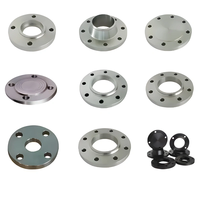
The six common types of flanges used in process piping are weld neck, slip-on, socket weld, threaded, lap joint, and blind flanges. Specialty designs include long weld neck, reducing, expander, and orifice flanges, while spectacle blinds, spades, and spacers are line-isolation devices commonly discussed with flange types.
Keep the terms separate when you specify a joint. Weld neck and slip-on describe how a flange connects to pipe, while blind describes the closure function of the component. Raised face, flat face, and ring-type joint describe the sealing surface.
ASME pressure class and API rated working pressure belong to different rating systems. Treating these labels as interchangeable can produce a connection that does not fit, seal, or meet the project specification.
This guide compares 11 flange and flange-related designs by connection or function, service characteristics, limitations, and RFQ inputs. Your final choice still depends on the governing code and standard, pressure and temperature, pipe dimensions, fluid, material, external loads, fatigue, fabrication method, inspection, and the mating connection.
Key Takeaways
- The flange type, face, rating, material, and standard are five separate selection decisions.
- Weld neck flanges are a common starting point for demanding pressure, temperature, cyclic, or high-load service, but the piping specification controls the final selection.
- Slip-on flanges simplify fit-up; socket weld and threaded flanges are generally used for smaller-bore applications within code and project limits.
- Lap joint assemblies use a stub end and rotating backing flange, which can help alignment and control the use of costly alloy material.
- API 6A Type 6B and Type 6BX flanges are wellhead and tree equipment connections. Do not select them by converting API working pressure into an ASME class.
- A complete RFQ identifies the standard and edition, type, size or bore, pipe schedule, rating, face, material, gasket or ring, bolting, inspection, documents, and mating connection.
What Is a Flange?
A flange is a projecting rim or connection component used to join pipe, valves, pumps, vessels, manifolds, and other equipment. Two compatible flange faces normally clamp a gasket or metal ring with bolts or studs. The joint can then be assembled, inspected, and dismantled without cutting the piping.
The flange is only one component of the connection. Sealing also depends on the mating face, gasket or ring, bolting, surface finish, alignment, assembly procedure, and operating conditions. For terminology covering the hub, face, bore, bolt circle, holes, and other features, see the flange parts guide. The separate how flanges work article explains how the bolted joint operates.
Keep Flange Type, Face, Rating, Material, and Standard Separate
| Selection Item | What It Defines | Examples |
| Flange type | How the component connects or what function it performs | Weld neck, slip-on, socket weld, threaded, lap joint, blind |
| Face | How the joint seals | Raised face, flat face, ring-type joint |
| Rating | The pressure-temperature rating system used by the standard | ASME Class 150–2500; API rated working pressure |
| Material | Metallurgy and specified properties | Carbon steel, low-temperature steel, stainless steel, duplex or nickel alloy |
| Standard | Dimensional and technical rules | ASME B16.5, ASME B16.47, API 6A or EN 1092-1 |
You need all five fields to define a flange. “Four-inch RTJ flange” remains incomplete because RTJ is a facing, not an attachment method, and the phrase does not identify the standard, rating, bore, material, or ring groove.
Quick Comparison of 11 Flange and Flange-Related Designs
| Design | Connection or Function | Service Characteristic | Main Limitation or RFQ Check |
| Weld neck | Butt-welded tapered hub | Common choice for demanding pressure, temperature, cyclic, or external-load duty | Match bore and weld end to pipe schedule; define NDE |
| Slip-on | Pipe passes through bore; fillet welded | Simpler alignment for suitable general service | Confirm code limits, weld access, insertion, and setback |
| Socket weld | Pipe enters a socket; external fillet weld | Compact small-bore welded connection | Define assembly gap; evaluate crevice and cleanliness risks |
| Threaded | Internal thread joins threaded pipe | Assembly without welding | Specify exact thread form and permitted service |
| Lap joint | Loose backing flange with stub end | Rotating alignment and alloy-cost control | Order a compatible stub end and backing flange |
| Blind | Solid bolted closure | Isolation, test boundary, or future access | Define facing, thickness or standard, tapping, and handling |
| Long weld neck | Extended integral neck | Equipment or vessel nozzle connection | Provide neck length, bore profile, wall, and drawing |
| Reducing | Standard flange pattern with smaller bore | Compact size reduction | State both sizes; review flow, erosion, and process effects |
| Expander | Smaller pipe transitions to larger flange end | Compact expansion with fewer welds | Check transition stress, geometry, and availability |
| Orifice | Paired flanges with pressure taps | Differential-pressure flow measurement | Specify the complete metering assembly and tap orientation |
| Spectacle blind | Visible open or closed line blank | Positive visual line isolation | Match flange rating and allow joint-spreading space |
The Six Main Types of Flanges
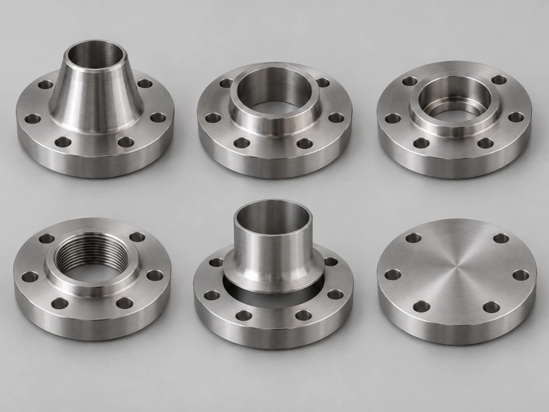
Weld Neck Flange
A weld neck flange has a tapered hub and joins the pipe with a full-penetration butt weld. The flange bore is specified to match the pipe bore for the selected schedule or wall thickness, producing a smoother internal transition than a connection with an internal ledge.
You will often consider this design for high pressure, temperature extremes, cyclic loading, vibration, bending, or other demanding service. The hub transfers load between the flange and pipe, while the butt weld can be examined by the method required in the piping specification.
The trade-off is that the connection requires more exacting fit-up, welding, and inspection. State the pipe schedule or wall thickness so the bore and weld preparation match the pipe.
Slip-On Flange
A slip-on flange has a bore larger than the pipe outside diameter, allowing it to slide over the pipe for alignment. It is normally secured by internal and external fillet welds, subject to the applicable fabrication rules.
This design can suit general industrial service where fit-up speed matters and the design conditions permit a slip-on connection. Compare total installed cost rather than flange price alone: two weld locations, internal setback, surface protection, and inspection affect fabrication.
Confirm fluid service, pressure, temperature, fatigue, corrosion allowance, external loads, and examination requirements before selection.
Socket Weld Flange
A socket weld flange contains a machined recess. The pipe enters the socket and is withdrawn to the assembly gap required by the approved procedure before the external fillet weld is made. It is generally associated with smaller-bore welded piping.
The socket creates a crevice that may matter where fluid promotes crevice corrosion, solids can collect, or cleanliness is critical. Specify nominal pipe size, schedule, material, rating, facing, and socket dimensions. Socket weld and slip-on flanges are not interchangeable merely because both use fillet welds.
Threaded Flange
A threaded flange screws onto externally threaded pipe and allows assembly without a welded attachment. It can be useful where hot work is restricted, or the material is difficult to weld.
Threaded flanges are normally considered for smaller sizes and less severe duties within the governing limits. Threads reduce the effective pipe wall and may loosen or leak under temperature cycling, vibration, bending, or repeated assembly. Specify the exact thread standard and form. NPT, BSPT, and other thread systems are not automatically compatible, and sealant cannot correct a mismatched connection.
Lap Joint Flange
A lap joint assembly uses a stub end butt-welded to the pipe and a loose backing flange behind it. The backing flange can rotate, which simplifies bolt-hole alignment and repeated dismantling.
The arrangement can also limit the amount of expensive alloy in the joint because the wetted stub end may match the process material while the backing flange uses another permitted material. The stub end forms the sealing surface, so specify the two parts as one compatible assembly, including stub-end type and length, lap thickness, corner radius, finish, gasket, backing-flange bore, and rating.
Blind Flange
A blind flange is a solid closure for a pipe, valve, vessel nozzle, or equipment opening. Its bolted construction allows removal for inspection, cleaning, testing, or future expansion.
Blind flanges carry bending from pressure and bolt loading. Large, high-rated components can be heavy, so plan lifting, handling, bolting, and safe removal. A tapped blind requires controlled drawing and machining for the vent, drain, instrument, or test connection. Never loosen a blind until the isolated volume is depressurized, drained, and verified under the site procedure.
Specialty Flange Designs and Line-Isolation Devices
Long Weld Neck Flange
A long weld neck flange extends the hub and is commonly used as an equipment or vessel nozzle. The extended neck may replace a separate pipe neck and flange combination. Provide the full neck length, bore profile, wall thickness, weld end, facing, material, and design basis because nominal size and class may not define a project-drawing item.
Reducing Flange
A reducing flange combines a larger flange pattern with a smaller bore. It can save space compared with a separate reducer, but the abrupt area change may affect pressure loss, turbulence, erosion, or solids accumulation. State both the flange size and reduced bore, pipe schedule, facing, rating, material, and flow direction when relevant.
Expander Flange
An expander flange uses a weld-neck-style transition from smaller pipe to a larger mating flange. The compact design can reduce weld count and overall length in some layouts. Confirm transition geometry, stress, flow effects, availability, and the applicable manufacturer or project standard.
Orifice Flange
An orifice flange set supports an orifice plate for differential-pressure flow measurement. The pair includes controlled pressure-tapping provisions and requires the correct bore, plate, gasket, tap orientation, and installation arrangement on both the upstream and downstream sides. Specify the metering standard, line size and schedule, rating, facing, material, taps, plate, jack screws when required, and inspection documents.
Spectacle Blinds, Spades, and Spacers
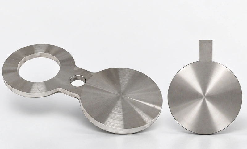
Spectacle blinds, spades, and spacers provide visible line isolation between two flanges. A spectacle blind joins a solid blade and an open ring; rotating it places either the closed or open side in the line. Separate spades and spacers provide the same two conditions as individual components.
These are line blanks rather than pipe-attachment flange types, but procurement teams often group them with flange designs. Specify the mating flange standard and rating, line size, thickness, material, surface finish, handle arrangement, and identification. The layout must provide enough space for controlled joint spreading and changeover.
Flange Face Types: RF, FF, and RTJ
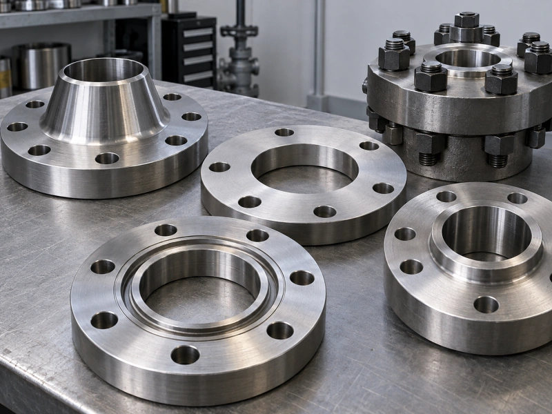
The flange face defines where and how the joint seals. It must match the mating component, gasket or ring, rating, material, finish, and service. This section provides a brief selection boundary; for a full comparison, see the flange face types guide.
| Face | How It Seals | Selection Boundary |
| Raised Face (RF) | A raised gasket seating area concentrates bolt load over a smaller area | Match the gasket type, finish, rating, and mating face |
| Flat Face (FF) | The sealing surface remains in the same plane as the surrounding face | Often uses a full-face gasket; follow equipment and material limits |
| Ring-Type Joint (RTJ) | A machined groove contains a metal ring gasket | Match groove and ring designation; R, RX, and BX are not general substitutes |
RTJ is a facing and sealing system, not an attachment type. A flange can be both weld neck and RTJ, or blind and RTJ. For a focused sealing comparison, use the RF versus RTJ flange guide.
ASME Pipe Flanges and API 6A Connections
| System | Typical Scope | Rating and Connection Check |
| ASME B16.5 | Pipe flanges and flanged fittings from NPS 1/2 through NPS 24 | Use the applicable material group and pressure-temperature rating tables; specify class and face |
| ASME B16.47 | Large-diameter steel flanges from NPS 26 through NPS 60 | Specify Series A or Series B because dimensions differ |
| API Specification 6A | Wellhead and tree equipment connections, including Type 6B and Type 6BX | Specify nominal bore, rated working pressure, ring, material class, temperature class, PSL, and mating equipment |
Do not convert an API rated working pressure into an assumed ASME class or expect similar nominal sizes to mate. The two systems can differ in bolt pattern, bore, face, groove, dimensions, and rating basis. Use the API versus ASME flange comparison to understand where each system applies and the API 6B versus 6BX guide to compare the API connection families.
Standards change. Confirm the contract edition and applicable addenda, errata, purchaser supplements, and project requirements. The flange standards guide maps the main standards without reproducing controlled standard tables.
How to Choose the Right Type of Flange?
Start with Governing Documents
Check the piping code, line class, equipment specification, datasheet, drawing, and purchaser requirements. These documents may already limit the flange type, face, material, and rating.
Define Pressure and Temperature Together
Provide design pressure, design temperature, operating range, upset conditions, vacuum when applicable, and pressure cycling. Select the rating from the correct standard for the specified material group. The flange pressure class guide explains why class is not a direct psi value.
Confirm Pipe and Mating Dimensions
State nominal pipe size, outside diameter, schedule or wall thickness, required bore, corrosion allowance, and the mating connection. Weld neck, socket weld, reducing, and expander designs depend directly on these dimensions.
Describe the Fluid and Environment
Identify the process fluid, concentration, water, solids, H2S or CO2 exposure, chlorides, cleaning chemicals, and external environment. The specification may require corrosion allowance, hardness control, impact properties, sour-service controls, overlay, cladding, coating, or corrosion-resistant alloy. Use the flange materials guide to organize material requirements, but do not treat a generic material list as a substitute for project-specific material selection.
Check Loads, Fabrication, and Access
Include piping weight, thermal movement, vibration, pulsation, bending, nozzle loads, wind or seismic loads, and cyclic duty. Confirm whether welding is allowed, what procedures and qualifications apply, the required NDE, lifting needs, tool clearance, insulation, coating repair, and future maintenance access. A pressure rating alone does not demonstrate suitability for every external-load combination.
Select the Complete Bolted Joint
Treat the mating flanges, gasket or ring, studs, nuts, lubricant, and tightening procedure as one joint. Confirm face compatibility, surface finish, gasket dimensions or ring number, bolt material and coating, and the approved assembly method.
Flange RFQ Checklist
- Governing standard and edition
- Flange type and face
- Nominal size or API nominal bore
- Pipe schedule, wall thickness, or required bore
- ASME class or API rated working pressure
- Material grade, heat treatment, impact, and hardness requirements
- Fluid, design pressure and temperature, external environment, and sour-service requirements
- Gasket or ring designation and bolting scope
- Quantity, mating connection, and approved drawing for nonstandard items
- NDE, dimensional inspection, testing, marking, traceability, and document requirements
- Third-party inspection, preservation, packing, destination, and delivery terms
Agree on all special marking, traceability, inspection, and data-book requirements before manufacturing; they may be impossible to verify retrospectively. The flange marking guide explains the identification fields to confirm.
Common Flange Selection Mistakes
| Mistake | Why It Fails | Correct Action |
| Calling RTJ a flange type | RTJ defines the sealing face, not the pipe attachment | Specify both the flange type and the facing |
| Treating class as psi | Allowable pressure varies with material, temperature, and standard | Use the applicable pressure-temperature rating basis |
| Ordering by nominal size | Size alone does not define bore, class, face, bolt pattern, or standard | Specify the complete connection |
| Mixing standards or series | ASME, API, EN, JIS, and B16.47 series use different dimensions and rules | Confirm both mating components and any engineered adapter |
| Ignoring the joint system | A flange cannot correct the wrong gasket, ring, bolting, finish, or alignment | Review the assembled bolted joint |
FAQ
What Are the Main Types of Flanges?
The six main pipe flange types are weld neck, slip-on, socket weld, threaded, lap joint, and blind. Specialty designs include long weld neck, reducing, expander, and orifice flanges. Spectacle blinds, spades, and spacers are line-isolation devices commonly discussed with flange types.
Which Flange Type Is Best for High-Pressure Service?
There is no universal answer based on type alone. A weld neck flange is often considered for demanding process piping, while an API 6A Type 6B or 6BX connection may apply to wellhead and tree equipment. Confirm the governing standard, material, temperature, size, external loads, fatigue, face, gasket or ring, and project specification.
What Is the Difference Between Weld Neck and Slip-On Flanges?
A weld neck flange butt-welds to the pipe through a tapered hub. A slip-on flange slides over the pipe and is normally secured with fillet welds. Weld neck designs are commonly selected for more demanding loading or cyclic service conditions; slip-on designs can simplify alignment where the project permits them. Compare fabrication and inspection cost, not only purchase price.
Is RTJ a Separate Flange Type?
No. RTJ is a flange face and sealing arrangement using a metal ring in matched grooves. You must still specify the structural type, such as weld neck or blind, plus the correct ring designation.
Can API and ASME Flanges Connect Directly?
Do not assume direct compatibility. Bolt patterns, bores, faces, grooves, dimensions, and rating systems may differ even when labels appear similar. Use an engineered adapter or crossover designed for the two exact connections when a transition is required.
What Should You Send to a Flange Manufacturer?
Send the standard and edition, type, size or bore, pipe schedule, rating, face, material, service conditions, gasket or ring, mating connection, quantity, drawing, inspection and testing scope, marking, documents, packing, and delivery terms.
Choose the Flange as a Complete Connection
Knowing the names of the types of flanges is only the first step. A weld neck, slip-on, or blind flange performs as intended only when its standard, dimensions, rating, face, material, gasket, bolting, and mating component belong together. Start with the design documents and real service conditions, then define every connection field in the RFQ and ask the supplier to list assumptions or deviations.
For oilfield connections, review AlienFrac’s API flanges manufacturing page and API 6A flange product range. These pages cover the commercial and product scope, while this guide focuses on general flange-type comparison and selection.
Send the flange standard, size or bore, rating, face, material class, temperature, fluid, mating connection, quantity, drawing, inspection plan, and document list through Contact Us for an application-specific review and quotation.