
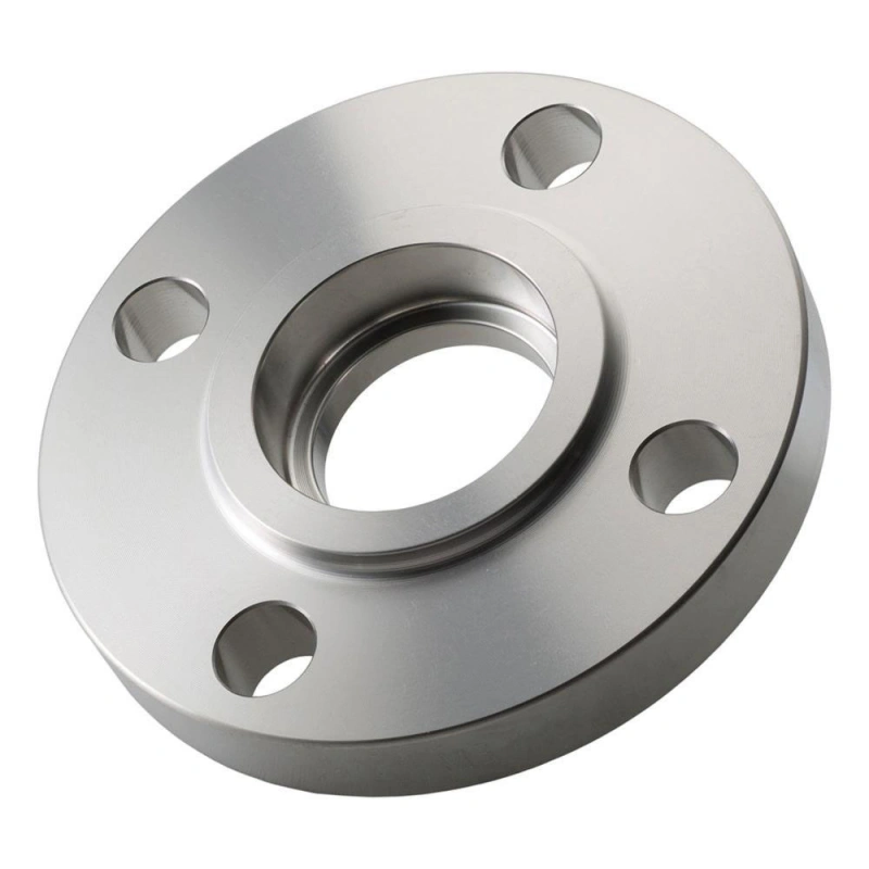
A flange is a projecting rim or a purpose-made ring that lets you connect one component to another. In a piping system, it usually provides a machined face and bolt pattern so you can join pipes, valves, pumps, pressure vessels, and wellhead equipment. Two mating flanges are brought together with the correct gasket or seal ring and bolting.
When you tighten the bolts correctly, the joint develops the compressive load needed to contain the fluid.
That removable connection is the main advantage. You can open a flanged joint for inspection, cleaning, equipment replacement, or a system modification without cutting out an entire piping section. However, a flange does not create a reliable seal by itself. The flange, sealing element, bolting, surface finish, alignment, and assembly procedure must work as one system.
Key Takeaways
- A flange gives you a standardized, removable way to connect pipes and equipment.
- A complete flanged joint normally includes two mating flanges, a gasket or seal ring, and compatible bolting.
- Weld neck, slip-on, socket weld, threaded, lap joint, and blind flanges solve different installation and service problems.
- Size and pressure class are not enough for selection. You must also match the standard, material, face, bore, temperature, fluid, and mating component.
- ASME pipe flanges and API 6A wellhead flanges serve different systems and should not be assumed to mate.
- Good alignment, clean faces, a suitable seal, and controlled bolt tightening are essential for a dependable joint.
What Is a Flange in a Piping System?
In practical terms, a pipe flange is a mechanical connection point. It is commonly round, has a central bore for the process flow, and carries bolt holes around its outside diameter. Depending on the design, you weld it to pipe, screw it onto a threaded pipe, use it with a stub end, manufacture it as part of a valve or fitting, or install it as a solid closure.
You usually choose a flange where you expect the system may need to come apart. Typical locations include:
- pump suction and discharge nozzles;
- valve and flow-meter connections;
- heat exchangers and pressure vessels;
- manifolds, separators, and skid packages;
- wellhead and Christmas tree equipment;
- pipeline branches and removable spool pieces; and
- line ends that need a blind closure for isolation or testing.
A welded joint may be more compact and permanent, while a union or coupling can be convenient in smaller or lower-duty lines. A flange earns its place when you need a strong pressure boundary combined with controlled assembly and future access.
How Does a Flange Joint Work?
A flange joint works by converting bolt tension into clamping force. As you tighten the bolts or studs, they stretch slightly. That elastic stretch pulls the mating flanges together and compresses the gasket or seal ring between the faces.
The sealing element fills or bridges the designed sealing area. In a raised-face joint, a gasket is compressed between the raised faces. In a ring-type joint, a metal ring is seated in accurately machined grooves. Internal pressure then tries to separate the joint, while the remaining bolt load and seal response keep the pressure boundary closed.
You get reliable performance only when the joint components are compatible. A correct flange with the wrong gasket can leak. The right gasket on damaged or misaligned faces can also fail. Uneven tightening may overload one part of the gasket while leaving another part under-compressed.
You should therefore treat the connection as a bolted flange joint, not as two pieces of steel and a gasket.
What Are the Main Parts of a Flange?
Understanding the main flange parts helps you read a drawing, check a quotation, and inspect a delivered product.
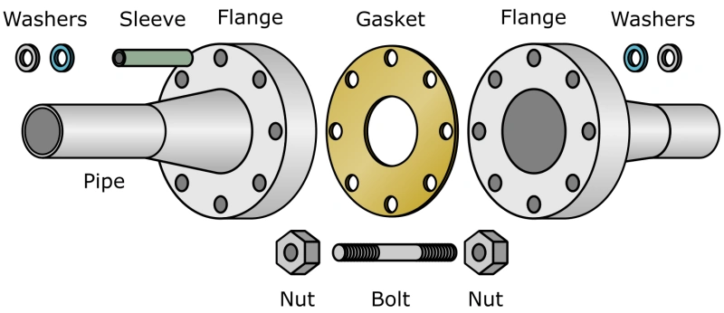
| Flange feature | What it means for you |
|---|---|
| Face | The machined sealing surface that meets the gasket or seal ring |
| Bore | The central opening; it must suit the pipe bore, schedule, or equipment passage |
| Hub or neck | The transition between the flange ring and the pipe connection; common on weld neck designs |
| Outside diameter | The overall flange diameter defined by the applicable standard or design |
| Thickness | A key dimension that contributes to flange strength and stiffness |
| Bolt circle | The imaginary circle passing through the centers of the bolt holes |
| Bolt holes | Openings for studs or bolts; their quantity, diameter, and spacing must match the mating flange |
| Ring groove | A precision-machined groove used with an RTJ metal ring |
| Marking area | The location for manufacturer, material, size, rating, heat, and standard information |
On a weld neck flange, you should also confirm the weld-end preparation and bore. If the bore does not match the pipe schedule, you may create an internal step that increases turbulence and complicates welding.
What Are the Most Common Types of Flanges?
The word “type” usually describes how the flange attaches to the pipe or what job it performs. You can explore a more detailed comparison in Alienfrac’s guide to types of flanges, but the following overview covers the designs you will see most often.
Weld Neck Flange
A weld neck flange has a long, tapered hub and is butt-welded to the pipe. The gradual transition helps distribute stress between the flange and pipe, while a matched bore supports smoother flow.
You normally choose a weld neck flange for high-pressure, high-temperature, cyclic, or critical service. It requires accurate alignment and a qualified butt weld, so installation costs can be higher than for a slip-on flange. In return, you get a robust connection with good fatigue performance.
You encounter many flange types in industrial piping systems. Each flange type serves a unique purpose and fits specific conditions. When you select flanges, you must consider the mechanical properties, installation requirements, and maintenance needs.
Slip-On Flange
A slip-on flange slides over the pipe and is typically secured with fillet welds. It is easier to position before welding and often costs less to install.
You may select it for suitable low- or moderate-duty services where project specifications allow it. You should not assume it is interchangeable with a weld neck flange simply because the size and class match. Attachment strength, fatigue resistance, bore arrangement, and service restrictions are different.
Socket Weld Flange
A socket weld flange has a recessed socket that accepts the pipe end. A fillet weld secures the pipe at the hub.
This design can work well on small-bore, higher-pressure piping. However, the internal crevice makes it a poor choice for some corrosive, erosive, or hygienic services. The installation procedure also needs the specified expansion gap before welding.
Threaded Flange
A threaded flange screws onto a pipe with matching external threads. You can install it without a flange-to-pipe weld, which is useful where hot work is restricted or field welding is impractical.
You should check pressure, temperature, vibration, cyclic loading, fluid hazard, thread form, and local code restrictions before choosing it. Threaded connections are normally limited to applications where the governing specification accepts them.
Lap Joint Flange
A lap joint assembly uses a loose backing flange with a stub end. The backing flange can rotate, making bolt-hole alignment easier. Only the stub end contacts the process fluid in a typical arrangement.
You may use this design when the line needs frequent dismantling or when an expensive corrosion-resistant material is required only for the wetted stub end. The two-piece construction is convenient, but you still need to evaluate pressure, fatigue, and project limitations.
Blind Flange
A blind flange is a solid closure with no flow bore. You use it to close a pipe end, valve outlet, vessel nozzle, or test boundary.
Blind flanges can experience high bending stress because pressure acts across the full closed area. You must select the correct standard, size, rating, material, and facing rather than treating a blind as a simple cover plate.
What Flange Face Types Should You Know?
The flange face determines where and how the sealing element is loaded. It must match the mating face and the specified gasket or ring.
Raised Face
A raised-face (RF) flange has a sealing area raised above the bolting circle. Concentrating the bolt load on this smaller area helps compress the gasket. RF flanges are common in ASME process piping.
Flat Face
A flat-face (FF) flange has a sealing face in one plane across the flange. It is often paired with a full-face gasket and is commonly associated with cast iron, nonmetallic equipment, and lower-pressure services.
You should not mate an RF flange to an FF flange unless the equipment manufacturer and engineering specification explicitly allow the arrangement.
Ring-Type Joint
A ring-type joint (RTJ) flange uses a machined groove and a metal ring. You will see RTJ connections in high-pressure and high-temperature oil and gas service. Groove geometry, ring number, material, hardness, and surface condition all matter.
API 6A Type 6B and 6BX flanged end connectors also use specific ring-joint arrangements. They are not simply ASME RTJ flanges with a different pressure label. If you are buying API wellhead flanges, confirm the exact API type, bore, rated working pressure, material class, temperature class, product specification level, performance requirement level when applicable, and mating equipment details.
For a closer comparison of common sealing surfaces, see Alienfrac’s guide to flange faces.
Flange Standards: API vs ASME
Standards give you dimensional rules, materials or material groups, ratings, tolerances, markings, and other requirements. A standard designation is part of the product identity, not a paperwork detail.
| Topic | ASME B16.5 / B16.47 | API Specification 6A |
|---|---|---|
| Main use | General refinery, chemical, power, utility, and industrial piping | Wellhead and Christmas tree equipment |
| Size system | Nominal Pipe Size (NPS) | API equipment sizes and bores |
| Rating format | ASME pressure class with material-specific pressure-temperature tables | Rated working pressure and API product requirements |
| Typical faces/connectors | RF, FF, and RTJ, depending on type and class | API 6B and 6BX flanged end connectors with specified ring joints |
| Selection focus | Piping code, class, material group, temperature, size, type, and face | Equipment configuration, pressure rating, material class, temperature class, PSL, PR level where applicable, and connector details |
| Interchangeability | Only when the standard, size, class, face, dimensions, and material requirements match | Only with the correct API type, size or bore, pressure rating, ring, and mating connector |
ASME B16.5 covers pipe flanges and flanged fittings from NPS 1/2 through NPS 24. ASME B16.47 covers large-diameter steel flanges from NPS 26 through NPS 60. API Specification 6A addresses wellhead and tree equipment, including its standardized end connectors.
Most importantly, an ASME class is not a fixed pressure in psi. The allowable pressure depends on material group and temperature. “Class 600” does not automatically mean a maximum of 600 psi. You must use the pressure-temperature table in the applicable edition and check the governing piping code and project specification.
For oilfield projects, use Alienfrac’s comparison of API vs ASME flanges as a starting point, then verify the purchase specification against the current governing standard.
What Materials Are Flanges Made From?
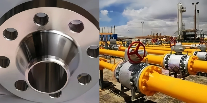
Flange material must be compatible with the connected pipe or equipment, design temperature, process fluid, external environment, welding procedure, and applicable standard.
Common choices include:
- forged carbon steel for general oil, gas, water, and process service;
- low-temperature carbon steel where impact toughness is required;
- stainless steel for improved corrosion resistance;
- alloy steel for elevated-temperature or higher-strength service;
- duplex and nickel alloys for aggressive corrosion conditions; and
- cast iron, ductile iron, aluminum, or nonmetallic materials in suitable specialized systems.
For ASME piping, you may see specifications such as ASTM A105, ASTM A350, or ASTM A182, depending on service and grade. API 6A equipment uses its own material classes and product requirements. If hydrogen sulfide is present, you also need to confirm the project’s sour-service material, hardness, testing, and documentation requirements.
Do not select material from a generic “corrosion-resistant” label. Ask what fluid touches the flange, at what concentration, pressure, and temperature, and whether the external environment creates additional corrosion risk. Alienfrac’s flange material guide provides a useful overview of these choices.
How Do You Choose the Right Flange?
You can reduce specification errors by making your selection in a fixed order.
- Identify the governing standard and code. Start with API, ASME, EN, JIS, or the project-specific requirement. Do not try to make the standard fit after choosing dimensions.
- Confirm the service. Record the design pressure, design temperature, operating cycles, fluid, corrosion conditions, external loads, and maintenance needs.
- Set the size and bore. Check NPS or API bore, pipe schedule, inside diameter, and the mating equipment opening.
- Choose the type and attachment. Decide whether you need weld neck, slip-on, socket weld, threaded, lap joint, blind, or an API-specific connector.
- Select the rating correctly. For ASME products, use the material-specific pressure-temperature tables. For API equipment, use the required rated working pressure and product configuration.
- Match the face and sealing element. Specify RF, FF, RTJ, API ring groove, gasket dimensions, ring number, surface finish, and compatible materials.
- Select material and manufacturing route. State the material specification, grade, heat treatment, forging requirements, and any sour-service controls.
- Check bolting and joint compatibility. Confirm stud size, length, grade, coating, nut grade, lubrication assumptions, and tightening procedure.
- Define inspection and documentation. Include dimensional inspection, material traceability, NDE, hardness or mechanical testing, pressure testing when applicable, marking, certificates, and third-party inspection.
- Verify the mating flange before release. Compare the bolt circle, hole count, outside diameter, face, groove, bore, rating, and standard on both sides.
If you are sourcing oilfield connectors, a complete datasheet or mating drawing is much safer than an email that says only “4-inch high-pressure flange.”
What Should You Check During Installation?
Even a correctly manufactured flange can leak if it is assembled poorly. Before bolt-up, you should:
- isolate, depressurize, drain, and verify the system is safe to work on;
- inspect the flange faces and ring grooves for damage, corrosion, debris, and coating overspray;
- confirm the two flanges are aligned without using the bolts to pull the piping into place;
- verify the gasket or ring is new, correct, clean, and centered;
- check bolt, stud, nut, washer, and lubricant requirements;
- hand-tighten, then apply the approved multi-pass cross-pattern sequence;
- use the specified torque or tensioning method and calibrated tools; and
- complete the required inspection and leak or pressure test.
You should never guess a torque value from flange size alone. The correct assembly load depends on the joint design, bolt material, gasket or ring, friction or lubricant, tightening method, and governing procedure.
After commissioning, inspect critical connections for leakage, corrosion, bolt condition, coating damage, and signs of movement. If you reopen a joint, replace the gasket or seal ring unless an approved engineering procedure specifically permits reuse.
Why Are Flanges Important in Oil and Gas?
In oil and gas operations, a flange often sits at a point where pressure containment and maintainability meet. You may find flanged connections on wellheads, Christmas trees, valves, chokes, manifolds, separators, meter skids, pressure vessels, and pipeline equipment.
The correct joint lets you isolate equipment, replace a valve, inspect a pressure boundary, or reconfigure a skid with less cutting and welding. In high-pressure service, it also gives you a connection whose dimensions, materials, marking, and testing can be controlled through a recognized standard.
That does not make every flange suitable for every oilfield duty. An ASME piping flange, an API 6A flange, an API 16A connector, and a proprietary compact connector may look similar from a distance while having different dimensions and qualification requirements. Your safest purchasing habit is to identify the equipment standard and mating connection before you request a quote.
FAQ
What is the simple definition of a flange?
A flange is a projecting rim or a manufactured ring that helps you connect, strengthen, locate, or seal components. In piping, it gives you a bolted connection point between pipes and equipment.
What is a flange used for?
You use a flange to connect pipe sections, valves, pumps, vessels, wellhead equipment, and other components. It also gives you a removable access point for inspection, cleaning, testing, isolation, or replacement.
What is included in a complete flange joint?
A typical joint includes two compatible flanges, a suitable gasket or seal ring, studs or bolts, nuts, and an approved assembly procedure. The flange faces, sealing element, and bolting must work together.
Is flange class the same as pressure in psi?
No. An ASME class designation is not a direct psi limit. The permitted pressure changes with material group and temperature, so you must consult the applicable pressure-temperature table. API 6A uses rated working pressures and product-specific requirements for wellhead and tree equipment.
What is the difference between a flange and a coupling?
A flange normally uses mating faces, bolting, and a gasket or ring, giving you a strong connection that can be dismantled deliberately. A coupling joins pipe by threads, grooves, compression, welding, or another mechanism. The right option depends on pressure, temperature, pipe size, fluid hazard, movement, and maintenance needs.
Can you connect any two flanges of the same size?
No. The nominal size may match while the bolt pattern, class or rated pressure, face, bore, material, standard, or ring groove differs. You should verify every mating dimension and specification before assembly.
How can you identify a flange?
Start with the markings. Depending on the standard, you may find the manufacturer, size, class or working pressure, material grade, heat number, flange type, standard, ring groove, and other traceability information. Compare those markings with the drawing and material certificate rather than relying on appearance alone.
Conclusion
When someone asks, “What is a flange?” the short answer is straightforward: it is a connection feature that lets you join components securely and, in many cases, take them apart later. The engineering answer is more useful. A reliable flange connection is a complete system of compatible faces, sealing elements, bolting, materials, dimensions, and assembly controls.
If you define the standard, service conditions, size, rating, face, material, bore, and inspection requirements before you buy, you avoid the most common fit-up and leakage problems.
For wellhead and tree applications, Alienfrac can manufacture API flanges to your specified connection details and documentation requirements. Send your datasheet or mating drawing so the quotation is based on the joint you actually need.