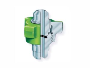
The FIG 206 hammer union provides a removable connection for manifolds and piping systems. An O-ring positioned on the sealing face of the male sub forms the sealing interface when the matched union components are made up.
The standard FIG 206 configuration is rated for 2,000 PSI non-shock cold working pressure (NSCWP) and tested at 3,000 PSI. Available sizes and dimensional information are listed below. For project orders, confirm the required end connections, service medium, temperature range, and operating conditions before production.
These specifications apply to the standard FIG 206 configuration shown here. Final configuration should be confirmed against the required connection type, materials, seal compound, service medium, temperature and operating conditions.
The FIG 206 uses an O-ring positioned on the sealing face of the male sub. When the union is fully made up, the O-ring forms the sealing interface between the matched union components.
Seal compound should be selected according to the service medium and operating temperature. For project or replacement orders, provide the fluid type and temperature range so the appropriate sealing material can be confirmed.
For butt-weld configurations, Schedule 40 is recommended where applicable. Alternative end configurations can be reviewed according to the piping system and mating connection requirements. For project-specific connections, provide the mating dimensions or connection specification so the configuration can be confirmed before production.
For an overview of common end configurations, see hammer union connection types.
FIG 206 is used for manifold and piping connections, including applications involving negative pressure or corrosive service. Suitability depends on the specific operating conditions and the materials used in the supplied configuration.
For vacuum or corrosive-service applications, confirm the operating pressure range, fluid composition, temperature, seal compound and union materials before production. Color coding can assist with figure identification, but the required figure and configuration should always be verified against the product specification and service requirements.
Use the nominal size to narrow your selection, then check the overall length and nut radius against the available installation clearance. The table below lists the metric dimensions and weights for the standard FIG 206 configuration.
For fabrication, replacement, or interchangeability decisions, confirm the final dimensions against the approved dimensional drawing for the union to be supplied.
| Nominal Size (in) | Nominal Size (mm) | Total Length (mm) | Nut Radius (mm) | Nut Material Code | Part Material Code | Weight (lb) | Weight (kg) |
|---|---|---|---|---|---|---|---|
| 1 | 25.4 | 68.3 | 49.2 | SC/SF | SF | 1.75 | 0.8 |
| 1½ | 38.1 | 73 | 60.3 | SF | SF | 2.37 | 1.1 |
| 2 | 50.8 | 84.1 | 73.8 | SF | SF | 5.25 | 2.4 |
| 2½ | 63.5 | 103.2 | 93.7 | SF | SF | 10 | 4.5 |
| 3 | 76.2 | 111.1 | 98.4 | SF | SF | 15.25 | 6.9 |
| 4 | 101.6 | 122.2 | 127 | SF | SF | 20 | 9.1 |
| 6 | 152.4 | 168.3 | 163.5 | SF | SF | 44.5 | 20.2 |
| 8 | 203.2 | 184.2 | 195.3 | SF | SF | 61 | — |
Dimensions and weights are configuration-specific. The kilogram weight for the 8 in size is not specified. Material codes are shown as listed; confirm the applicable material grade and approved dimensional drawing for the required size before fabrication, replacement, or interchangeability decisions.
The FIG 206 configurations listed here use material codes SC/SF or SF for the nut and SF for the other listed components. These codes should not be treated as material grade designations. If a specific material grade, certification, or service standard is required, include it in the RFQ for confirmation.
Standard FIG 206 color identification is a blue nut with gray union parts. Color coding can assist with figure identification, but it should not be used as the sole basis for product selection or interchangeability. Always verify the stamped figure number, nominal size, pressure rating, and supplied documentation.
For more information, see the hammer union marking guide.
Both FIG 200 and FIG 206 are rated at 2,000 PSI NSCWP with a 3,000 PSI test pressure, but they are intended for different connection requirements. FIG 200 is presented as a compact union for low-pressure kill lines and medium-pressure air, water, oil, or steam service. FIG 206 incorporates an O-ring on the male-sub sealing surface and is used for manifold and piping connections.
Because the two figures share the same pressure rating, selection should be based on the required connection geometry, sealing arrangement, service conditions, and approved dimensional drawing rather than pressure rating alone.
The sealing arrangement is different. FIG 206 uses an O-ring positioned on the sealing face of the male sub, while the FIG 207 hammer union uses an NBR sealing ring positioned on the shutoff head.
FIG 207 documentation also describes an interchange option for the threaded connector with FIG 200 and FIG 206. This should not be interpreted as interchangeability of the complete union assembly. Confirm component compatibility, mating dimensions, and the applicable drawings before replacement or assembly.
FIG 211 is designed for connections requiring electrical isolation. FIG 206 is not specified as an insulating union.
Where electrical isolation is part of the piping or equipment specification, select the appropriate insulating-union configuration and confirm the required FIG 211 documentation, materials, and connection details before supply.
Provide the nominal size, required quantity, and required end connection or mating-connection drawing. Include the maximum operating pressure, any vacuum conditions, test requirements, service fluid, temperature range, and any corrosion or sour-service requirements. Also specify the material certification, inspection records, or other project documentation required with the order.
For replacement applications that must mate with existing equipment, provide the figure number, nominal size, visible product markings, and available assembly or dimensional drawings. AlienFrac can then confirm the appropriate seal, materials, connection details, and FIG 206 configuration before quotation.
Do not assume interchangeability based only on the figure number, nominal size, or pressure rating. For replacement applications, confirm the mating dimensions, end connections, sealing arrangement, and applicable drawing against the installed equipment.
Some related figure configurations may share individual connection features, but this does not establish interchangeability of complete union assemblies. Component compatibility should be confirmed against the applicable dimensions and drawings before assembly or replacement.
Provide the figure number, nominal size, visible product markings, required quantity, end-connection details, and any available dimensional or assembly drawings. Service fluid, operating pressure, temperature, and project documentation requirements should also be included.
No. They are material codes used for the listed FIG 206 components and should not be treated as complete material-grade specifications. If your project requires a specific grade, material certificate, or service standard, state those requirements in the RFQ.
Color coding can assist with identification, but it should not be the sole basis for selection or replacement. Verify the stamped figure number, nominal size, pressure rating, connection details, and applicable documentation.
Provide the required end connection, mating dimensions, service fluid, operating pressure, temperature range, and any corrosion or sour-service requirements. AlienFrac can review these parameters and confirm the applicable configuration before quotation.
Send your required size, quantity, end connection, service conditions, and documentation requirements. AlienFrac will review the application, confirm the appropriate FIG 206 configuration, and provide a quotation based on your project requirements.
WhatsApp us