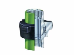
FIG 211 gives production piping a quick union connection while helping maintain electrical isolation at the joint. Compare sizes, seals, service limits, and ordering details.
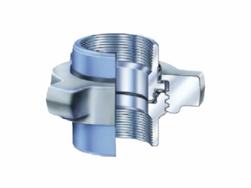
Alienfrac FIG 211 is a forged-steel insulating hammer union for piping systems where electrical isolation matters. Insulating components interrupt metal-to-metal contact across the joint, while an O-ring on the male sub and a separate seal ring on the female sub provide two sealing stages. The union is intended for verified 2,000 psi non-shock cold working pressure service.
Use this quick view to check whether FIG 211 fits the basic service. Final limits are controlled by the approved Alienfrac datasheet and order documents.
| Specification | Details |
|---|---|
| Product Type | FIG 211 insulating hammer union |
| Working Pressure | 2,000 psi NSCWP |
| Test Pressure | 3,000 psi |
| Nominal Sizes | 2″ and 3″ |
| End Connection | Threaded |
| Construction | Forged carbon-steel subs and nut with insulating components |
| Sealing | Male-sub O-ring plus female-sub insulating seal ring |
| Typical Identification | Blue subs and gray nut |
Pressure, temperature, thread, material, elastomer, dimensions, electrical performance, and test requirements must match the approved datasheet for the supplied product.
A conventional union can create an electrically continuous path across the connection. FIG 211 is designed for systems that need the joint to remain electrically isolated, including piping where cathodic protection is part of the corrosion-control plan. Its insulating components separate the metal parts at the joint while the wing-nut connection still allows practical make-up and break-out.
The insulating rings and seals interrupt direct metal-to-metal contact across the union. This helps the piping designer maintain the intended isolation boundary where stray current or electrolytic corrosion is a concern.
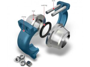
The male-sub O-ring forms the primary pressure seal. A separate seal ring in the female sub provides secondary sealing and electrical separation. Both wear parts can be inspected during scheduled maintenance and replaced with the correct compounds for the service.
The lugged nut gives trained crews a quick way to make up or break out the connection after the system has been isolated, drained, and fully depressurized. Correct identification and matched components remain essential.
FIG 211 is suited to verified 2,000 psi piping where both a quick union connection and electrical isolation are specified.
Do not use FIG 211 as a substitute for a higher-pressure drilling or stimulation union. For service above 2,000 psi, abrasive slurry, sour gas, unusual temperatures, or aggressive chemicals, ask Alienfrac to select the correct figure, material, and seal system.
During make-up, the nut draws the male and female subs together and loads the sealing elements. The O-ring on the male sub supplies the primary pressure barrier. The insulating seal ring in the female sub adds a second sealing barrier while keeping the metal components separated. Inspect both seals, the threads, lugs, and seating areas before every installation; replace damaged parts rather than forcing the connection together.
| Nominal pipe size | Total length | Nut radius | Materials | Weight | |||||
| in | mm | in | mm | in | mm | Nut | Part | lbs | kgs |
| 2 | 50.8 | 3 1/2 | 88.9 | 3 1/8 | 79.39 | SF | SF | 6.25 | 2.8 |
| 3 | 76.2 | 4 1/2 | 114.3 | 4 | 101.6 | 12.5 | 5.7 | ||
A figure number alone is not enough for a safe quotation. Send the complete operating envelope so the supplied union, seals, markings, and documents match the job.
Both figures are commonly associated with 2,000 psi service, but they solve different problems. FIG 206 is a general-purpose union with an O-ring-assisted seal for manifold, suction, and corrosion service. FIG 211 adds insulating components to break electrical continuity across the connection. Choose FIG 211 when the piping design calls for electrical isolation; choose FIG 206 when isolation is not required and its verified service envelope fits the job.
Hammer unions are pressure-containing components. Installation and maintenance must be performed by trained personnel under the site’s approved procedures.
Compare the full hammer union range, review pressure ratings and color codes, check connection types, or read the installation guide before selecting a union. For another 2-inch hammer union configuration, see the FIG 402 Hammer Union and confirm its pressure, connection, and service requirements for your application. For higher-pressure service, compare FIG 602 and FIG 1502 with the verified pressure and media requirements.
It is used in verified 2,000 psi piping where the connection must remain electrically isolated, such as production piping protected by a cathodic corrosion-control system.
The proposed Alienfrac page specifies 2,000 psi non-shock cold working pressure and a 3,000 psi test pressure. Confirm the applicable temperature, end connection, test method, and approved datasheet before use.
The proposed range is 2″ and 3″ with threaded ends. Ask for the current Alienfrac dimensional drawing and confirm the thread before ordering.
FIG 211 is built around electrical isolation at the connection. FIG 206 is a general-purpose O-ring-assisted union and normally retains a conductive metal path. Select by the piping design, not by pressure alone.
Do not assume interchangeability from the figure number alone. Verify the manufacturer’s written compatibility statement, figure, size, pressure rating, thread, sealing faces, markings, and condition of every component. Never mix unknown or damaged parts.
Only when the complete union is specifically ordered, manufactured, marked, and documented for the defined sour-service conditions. A standard-service FIG 211 must not be placed in H₂S service.
Tell us what the union will connect and the conditions it must handle. Alienfrac will review the size, thread, pressure, fluid, temperature, service class, quantity, and documentation before confirming a configuration.
WhatsApp us