
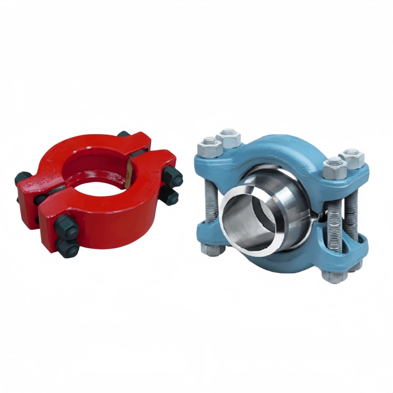
A frac hose is ordered as a complete assembly, not as a hose body with the end connections decided later. The connector affects pressure capacity, bore continuity, installed length, alignment, sealing, handling and whether the hose will mate with the equipment already on site. That is why a useful RFQ specifies End A and End B before production.
This guide explains how to compare frac hose connection types without reducing the decision to “hammer union vs flange.” Start with the hose duty, then match pressure class, nominal size, interface, seal, material and installation space. Use the product matrix and copy-ready checklist to turn those decisions into a quotation-ready specification.
Core principle: The approved assembly rating is limited by the lowest-rated component in the flow path. A 20,000 psi hose body does not make a 15,000 psi connector, adapter or mating component suitable for 20,000 psi service.
First Identify Which Frac Hose You Are Connecting?
“Frac hose” covers more than one service. A long-distance water-transfer hose, a high-pressure treatment hose and an acid suction/discharge hose do not use the same connection logic. Identify the duty before choosing a figure number, flange class or hub profile.
| Hose duty | Connection direction | Avoid this mistake |
| Layflat water transfer | Grooved couplings, plain ends or project-specific fittings where the selected product supports them | Do not apply 15K/20K treatment-line connection assumptions |
| High-pressure frac hose | Hammer union, API flange or hub, according to the selected assembly and mating equipment | Do not select the connector from hose pressure alone |
| High-pressure acid service | High-pressure end system plus a separate review of fluid, temperature and materials | Connection selection does not prove chemical compatibility |
| Acid suction/discharge or abrasive discharge | Published crimped coupling, union, flange or hub options for the exact product and pressure duty | Do not treat a transfer hose as a treatment line |
AlienFrac’s frac hose range separates water transfer, high-pressure pumping and acid-service paths. For acid duty, complete the broader acid fracturing hose requirements review before finalizing the ends.
Frac Hose Connection Types at a Glance
| Connection family | Best starting use case | RFQ variables | Installation check |
| Hammer union | Frequent field make-up and break-out where matched union halves are available | Exact FIG; size; pressure; male/female half; seal; material | Access for make-up; alignment; verified mating half |
| API flange | Bolted connection to a defined equipment flange or fixed pressure interface | Applicable specification; type/class; size; bore; face/profile; material | Bolt access; alignment; gasket/ring; installed rigid length |
| Hub | Selected high-pressure configurations with a matching hub system | Hub profile; bore; pressure; clamp/connector system; seal | Exact mating profile and project drawing |
| Transfer fitting | Layflat or lower-pressure transfer service | Coupling type; size; working pressure; retention method; fluid | Do not mix with treatment-line hardware |
No family is automatically safer, stronger or better in every installation. The right choice is the connection that matches the approved hose assembly, mating equipment and project requirements with enough room to install, inspect and maintain it correctly.
Hammer Union Connections
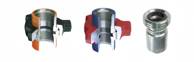
A hammer union can suit frac operations that require repeated rig-up and rig-down, but “hammer union” is not a complete specification. The union figure, nominal size, pressure rating, seal arrangement and both mating halves must agree. AlienFrac’s hammer union range is organized by figure; use that catalogue path only after the hose duty and system pressure are known.
FIG Number and Pressure Class
The FIG number identifies a defined union family. Similar appearance or nominal size does not make two figures interchangeable. Record the exact figure shown on the mating equipment or approved drawing, then verify its rating for the intended service.
AlienFrac publishes FIG 1502 hammer union for high-pressure oilfield use and lists fracturing and acidizing among its applications. The product page should be checked for the current size, pressure and material details. For 20K configurations, a product page may specify FIG 2002 instead; do not substitute FIG 1502 simply because it is already used elsewhere on the spread.
Size, Seal and Mating Half
Nominal hose ID and union size are related but not identical RFQ fields. Confirm the union interface, clear bore and mating equipment together. Also identify the male/female or threaded/weld-end arrangement, seal type, service material and any sour- or chemical-service requirement. If a drawing or marking is unclear, send a photograph with measured dimensions rather than guessing from color.
When Hammer Unions Fit Frac Operations
A matched union can be practical where the crew needs repeatable field connection and disconnection and the equipment already uses the same figure. Its value depends on correct identification, condition and installation—not on speed alone. Check that the hose can leave the rigid end without a tight bend or twist and that personnel can access the connection using the approved site procedure.
API Flange Connections
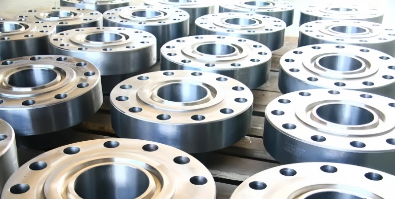
A flanged frac hose makes sense when the hose must bolt to a defined equipment flange or when the project drawing calls for a fixed flange interface. “API flange” is still incomplete: the applicable specification, type or class, nominal size, pressure rating, bore and face/profile must be stated. AlienFrac’s API flange options page provides the commercial flange family; the exact hose end remains subject to the selected product and assembly drawing.
Pressure Class and Flange Size
Match the flange to the complete system rating and the mating equipment—not only to the hose label. Confirm whether the equipment interface is an API 6A flange or another specified standard, then record the exact pressure class and size. A nominal hose bore does not, by itself, define the flange bore or outside dimensions.
Alignment, Bolting and Equipment Interface
A flange needs enough space for alignment, the sealing element and the approved bolting procedure. Check bolt access, equipment movement, flange orientation, gasket or ring requirements and the rigid length added by the hose end. A swivel or rotating feature should be treated as a product-specific option, not assumed. Where orientation matters, request a dimensioned assembly drawing before release.
When a Flanged Frac Hose Makes Sense?
Choose a flange when it is the defined mating interface and the installation provides room to align, bolt and inspect it. A flange is not automatically preferable for high pressure, just as a hammer union is not automatically limited to moderate pressure. Both can serve high-pressure systems when the exact product, rating and interface are approved. For a general—not frac-hose-specific—comparison, see flange vs union.
Hub Connections
AlienFrac lists hubbed end options on selected high-pressure frac hose pages. A hub should therefore be specified only where the proposed product and mating system support it. Provide the hub profile, nominal bore, pressure rating, seal arrangement and mating equipment drawing. “Hub connection” by itself is not enough because different profiles and connector systems may not mate.
The installation review should also account for the connector hardware, access and rigid-end length. If the website page does not publish the precise profile, state “verify against the exact product drawing and mating equipment” in the RFQ rather than naming an unconfirmed standard.
Layflat and Lower-Pressure Transfer Connections
Layflat water-transfer hoses and lower-pressure suction/discharge hoses belong to a different connection system from 15K or 20K treatment lines. Their ends may include grooved couplings, plain ends or project-specific fittings when the selected product supports them. Selection follows transfer pressure, vacuum where applicable, flow, retention method, deployment and mating equipment.
Do not choose a treatment-line hammer union or flange merely to make the connection name look familiar. Conversely, do not assume a transfer coupling is suitable for high-pressure pumping. The service rating and complete assembly design must remain aligned.
AlienFrac Frac Hose Connection Matrix
The matrix below uses current AlienFrac website product names and public connection statements. It is a route to the right product page, not blanket approval for every size-and-end combination. Always verify the selected part number and drawing.
| Website product | Service / pressure path | Published connection direction | Selection action |
| High Pressure Frac Hose | High-pressure fracturing fluid transfer; configuration-specific rating | Hammer union, hubbed or flanged ends; integral end fitting and in-line swivel listed as available features | Confirm exact assembly, pressure, bore and both ends |
| Super Abrasion Resistant Acid Fracturing Hose (Built-in) | Website table includes 15K and 20K entries | Built-in couplings; hammer unions, flanges and hubs listed | Match the connection to the exact table row and equipment |
| A801F Crimped Acid Fracturing Hose | 15K high-pressure acid/frac configurations shown | Product table lists FIG 1502 hammer-union and 15K API-flange directions for listed configurations | Verify part number, bore and connection row |
| A801T Double-Resin Crimped Hose | 15K and 20K high-pressure configurations shown | 15K entries list FIG 1502/API flange; selected 20K entries list FIG 2002/20K API flange | Do not transfer one size’s end option to another |
| A811 Acid Suction and Discharge Hose | 500 psi suction/discharge product | Crimped couplings, hammer unions, flanges and hubs listed as options | Treat as transfer duty; confirm exact proposed end |
| Product-data boundary: The website is the source of truth for product names and public end options. Do not infer that every listed connector is available at every size, pressure class or product row; obtain written confirmation for the exact assembly. |
Hammer Union vs Flange vs Hub: How to Choose
Use the connector already defined by the mating equipment unless the project has authorized an interface change. Then compare installation and operating constraints.
| Decision question | Hammer union | API flange | Hub |
| What must match? | FIG, size, pressure, halves, seal | Standard/type, class, size, bore, face/profile | Hub profile, bore, pressure, seal, connector system |
| Field make-up | Efficient where matched halves and procedure are established | Requires alignment, sealing element, bolts and access | Depends on the exact hub/connector hardware |
| Orientation | Verify hose clocking and mating-half geometry | Verify flange orientation and bolt access | Verify profile, clamp/connector access and drawing |
| Best reason to select | Existing matched union interface and repeat rig-up | Existing equipment flange or project-specified bolted joint | Approved compact hub system on the selected configuration |
Specify End A and End B Separately
A frac hose can have a hammer union at one end and a flange or hub at the other. End A and End B do not need to match, but each must match its own equipment interface and pressure requirement. Name the ends consistently on the drawing and RFQ.
| Field | End A | End B |
| Connection type | Hammer union / flange / hub / other | Hammer union / flange / hub / other |
| Nominal size | __________ | __________ |
| FIG number, if union | __________ | __________ |
| Flange specification / class | __________ | __________ |
| Hub profile, if hub | __________ | __________ |
| Pressure rating | __________ | __________ |
| Material and seal requirement | __________ | __________ |
| Orientation / clocking | __________ | __________ |
| Mating equipment / drawing | __________ | __________ |
Also define the finished overall length and measurement datum. Rigid end fittings, adapters and swivels affect the space available before the hose can enter its bend. A dimensioned interface drawing is especially useful when the two ends differ.
System Pressure Is Limited by the Lowest-Rated Component
The pressure system includes more than the hose body. The allowable assembly limit must account for the hose, End A, End B, adapters, seals, mating equipment and any project-specific approval or temperature limitation. One lower-rated item limits the complete flow path.
| Example: If a hose body is rated 20,000 psi but an installed connection or adapter is rated 15,000 psi, the assembly cannot be treated as a 20,000 psi system. The final approved rating must be established for the complete configuration. |
Provide normal working pressure, maximum expected pressure and transients in the RFQ. Proof and burst values are not normal operating ratings. If the pressure class is still being chosen, review 15,000 psi vs 20,000 psi frac hose before selecting the ends.
Connection Mistakes That Cause RFQ and Installation Problems
| Incomplete specification | Why it causes problems | Better RFQ entry |
| “Hammer union” | No FIG, size, rating, mating half or seal | Exact FIG + size + pressure + interface + seal/material |
| “API flange” | No specification/type, class, size, bore or face/profile | Complete flange designation plus equipment drawing |
| Hose pressure only | Connector, adapter or equipment may rate lower | List each component rating and approved system limit |
| End A assumed equal to End B | The two equipment interfaces may differ | Complete separate End A and End B fields |
| No overall-length datum | Rigid ends can change installed fit and bend zone | State datum and request assembly drawing |
| Adapter added after quotation | Adds interfaces, length and another rating limit | State whether adapters are permitted before design |
| Layflat end treated as 15K/20K end | The product and pressure systems are different | Identify hose duty before connection family |
Copy-Ready Frac Hose Connection RFQ Checklist
Copy these fields into an enquiry or purchase specification. Mark unknown items “to be confirmed” and attach equipment drawings or clear connection photographs where available.
- Hose duty / product family: _____________________________________________
- Fluid / service: ______________________________________________________
- Normal working pressure: __________ psi Maximum surge/transient: __________ psi
- Operating temperature min/max: __________________________________________
- Hose ID / clear bore: __________ Finished overall length and datum: __________
- Available bend / routing space and movement: _______________________________
- End A connection type: _________________________________________________
- End A size / FIG / flange class or hub profile: ______________________________
- End A pressure rating: __________ Seal / material: _________________________
- End A orientation / clocking: ____________________________________________
- End A mating equipment and drawing reference: ______________________________
- End B connection type: _________________________________________________
- End B size / FIG / flange class or hub profile: ______________________________
- End B pressure rating: __________ Seal / material: _________________________
- End B orientation / clocking: ____________________________________________
- End B mating equipment and drawing reference: ______________________________
- Adapters permitted? Yes / No If yes, approved type/rating: ____________________
- Assembly drawing required for approval? Yes / No
- Pressure-test certificate / documentation requirement: ________________________
- Marking, traceability or third-party witness requirement: _______________________
- Quantity: __________ Delivery destination / required date: ____________________
Send the completed checklist and drawings through AlienFrac Contact Us for product-level connection review and quotation.
FAQ
What connection types are used on frac hoses?
Depending on the hose duty and product, frac hose end connections may include hammer unions, API flanges, hubs, crimped couplings, grooved couplings, plain ends or project-specific fittings. Only treat an option as available when the selected product page or engineering quotation confirms it.
What is the difference between FIG 1502 and FIG 2002 on a frac hose?
They are different hammer-union figures used in different pressure/configuration paths. A801T product information, for example, lists FIG 1502 for selected 15K configurations and FIG 2002 for selected 20K configurations. Use the exact figure stated for the part number and mating equipment; do not interchange them.
Can a 15K hammer union be used on a 20K frac hose?
Not as a 20K assembly. A lower-rated connection limits the complete configuration. The final working-pressure rating must be confirmed for the hose, both ends, adapters, seals and mating equipment together.
When should I choose a flange instead of a hammer union?
Choose a flange when it matches the equipment or project-specified interface and there is adequate room for alignment, sealing and bolting. Choose a hammer union where a matched figure is already defined and repeated field make-up is part of the operating plan. The exact rating and product approval matter more than a generic preference.
Can a frac hose use a flange on one end and a hammer union on the other?
Yes, where the product and engineering design support that arrangement. Specify End A and End B independently and request a drawing showing the interfaces, orientation, overall length and approved assembly rating.
What information is required to specify End A and End B?
For each end, provide connection type, nominal size, FIG number or flange/hub designation, pressure rating, material, seal, orientation and mating equipment. Add the hose bore, overall length datum and whether adapters are allowed.
Does the hose pressure rating determine the connection rating?
No. Hose and connection ratings must be verified separately and then approved as one assembly. The lowest-rated component controls the system limit.
Are layflat frac hose connections the same as high-pressure frac hose connections?
No. Layflat water-transfer connections are selected for transfer pressure, flow, deployment and retention method. They should not be treated as interchangeable with 15K or 20K high-pressure treatment-line end systems.
How should frac hose connections be inspected?
Inspection should follow the manufacturer and site procedure for the exact connector. Typical checks include identification, sealing surfaces, threads or profiles, fasteners or union parts, deformation, corrosion, wear and evidence of leakage or movement. For broader hose inspection and storage guidance, see frac hose maintenance.
Conclusion
Selecting frac hose connection types is an interface-matching task. First identify the hose duty. Then define the system pressure, hose bore, equipment connection and installation space. Compare hammer union, API flange and hub options only after those requirements are clear.
Before ordering, complete End A and End B separately, identify the lowest-rated component and obtain an approved assembly drawing. That approach gives the supplier enough information to quote the right product path and gives the field team a connection that matches the equipment it will actually meet.