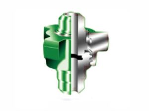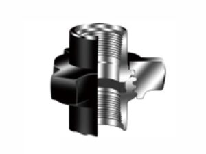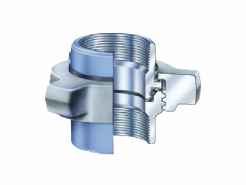
AlienFrac FIG 211 is a 2,000 PSI NSCWP insulating hammer union for connection points where metal-to-metal contact at the joint must be isolated. It has a 3,000 PSI test pressure and is available in 2 in. and 3 in. nominal sizes. The union uses SF steel-forging components and is identified by a gray nut with light blue parts. Send the required size, quantity, service conditions, and documentation needs for a quotation.
The FIG 211 connection uses an insulating design that removes metal-to-metal contact between the mating components at the joint. This is the model’s key functional distinction. If a project specification defines electrical-isolation criteria, provide the required values and service conditions for technical review before ordering.
No cathodic-protection performance, electrical certification or defined resistance value is specified for FIG 211. For a broader explanation of available joint configurations, see hammer union connection types.
FIG 211 uses a wear-resistant compound elastomer for sealing and includes a replaceable O-shaped seal assembly. The replaceable arrangement allows the identified sealing component to be renewed without treating the complete union as a single non-serviceable item.
When requesting a replacement seal, identify the figure number and nominal size. Do not order by visual similarity alone: seal geometry and compatibility must match the union and the intended medium. Inspect the seal and mating surfaces before assembly, and replace damaged components rather than forcing the joint together. General component terminology is explained in the Hammer Union Parts Guide.
FIG 211 is rated at 2,000 PSI NSCWP with a specified test pressure of 3,000 PSI. Final selection should consider the actual operating pressure, pressure cycles, medium, temperature, nominal size, adjoining equipment and project requirements.
Do not transfer ratings from FIG 200, FIG 206 or another figure simply because the unions appear similar. Verify the figure marking and system rating before installation. The hammer union pressure ratings and color codes guide provides broader selection context, while the values here apply specifically to FIG 211.
Within the AlienFrac hammer union range, FIG 211 is differentiated by its insulating connection design rather than by pressure rating alone.
FIG 211 is available in 2 in. and 3 in. nominal sizes. The nut and part material codes are SF for both sizes, and SF denotes steel forging. Use the dimensions below for preliminary comparison and RFQ preparation. If the union must mate with an existing assembly, provide a drawing, measured mating details or clear photographs for confirmation.
FIG 211 Hammer Union Dimensions and Specifications
| Nominal size (in) | Nominal size (mm) | Total length (in) | Total length (mm) | Nut radius (in) | Nut radius (mm) | Nut code | Part code | Weight (lb) | Weight (kg) |
|---|---|---|---|---|---|---|---|---|---|
| 2 | 50.8 | 3 1/2 | 88.9 | 3 1/8 | 79.39 | SF | SF | 6.25 | 2.8 |
| 3 | 76.2 | 4 1/2 | 114.3 | 4 | 101.6 | SF | SF | 12.5 | 5.7 |
Confirm the required FIG 211 configuration and mating dimensions during technical review.
FIG 211 is identified by a gray nut with light blue parts. Color can support field identification, but it should not be the only check because coatings may fade, become contaminated, or be repainted during service. Confirm the stamped figure number, nominal size, and pressure information as described in how to read hammer union markings.
FIG 211 is recommended for applications involving electrolytic corrosion. Its insulating connection is relevant where direct metal-to-metal contact at the union joint should be avoided.
No sour-service compliance, NACE qualification, corrosion-resistant-alloy construction, or universal suitability for corrosive media is specified for FIG 211. Provide the conveyed medium, operating pressure, temperature, and any project-specific corrosion or electrical-isolation requirements for technical review.
FIG 211 and FIG 206 hammer union are both rated at 2,000 PSI NSCWP with a 3,000 PSI test pressure, but they use different connection and sealing arrangements.
FIG 211 vs FIG 206
| Selection Point | FIG 211 | FIG 206 |
|---|---|---|
| Primary distinction | Insulating design removes metal-to-metal contact at the connection | O-shaped rubber ring is fitted on the male-connector sealing surface |
| Application focus | Applications involving electrolytic corrosion | Manifold and piping connections, including applications involving negative pressure and corrosion |
| Working pressure | 2,000 PSI NSCWP | 2,000 PSI NSCWP |
| Test pressure | 3,000 PSI | 3,000 PSI |
Select between the two figures according to the required connection design and service condition, not pressure rating alone.
Include the following information with your enquiry:
If a specific end-connection style is required, state it in the RFQ. A universal end-connection style is not specified for FIG 211, so the required configuration should be confirmed before ordering.
No. FIG 211 shares its 2,000 PSI NSCWP working pressure and 3,000 PSI test pressure with FIG 206, but the connection and sealing arrangements differ. Selection should be based on the required connection design and service conditions as well as pressure.
No defined electrical resistance value, cathodic protection performance, or electrical certification is specified for FIG. 211. If the project has electrical-isolation requirements, provide the required criteria and service conditions for technical review.
No sour-service compliance, NACE qualification or corrosion-resistant-alloy construction is specified for FIG 211. Provide the conveyed medium, temperature, pressure and applicable project requirements before ordering.
Do not treat FIG 211 and FIG 206 as interchangeable based only on pressure rating or appearance. Their connection and sealing arrangements differ, so the required figure and mating configuration should be confirmed before replacement.
Specify the FIG 211 figure number and nominal size when requesting a replacement seal. Seal geometry and compatibility should be confirmed for the union and intended medium rather than selected by visual similarity alone.
No. The gray nut and light blue parts can assist in identification, but coatings may fade, become contaminated, or be repainted. Verify the stamped figure number, nominal size, and pressure information before use.
Send the required size, quantity, operating conditions, and documentation needs to us. The requested FIG 211 configuration can then be reviewed before a quotation is provided.
WhatsApp us