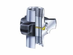
AlienFrac FIG 207 hammer unions use an O-shaped nitrile-butadiene rubber (NBR) sealing ring mounted on the shutoff head. The threaded connector is interchangeable with the corresponding threaded connectors of FIG 200 and FIG 206. FIG 207 is listed in 3 in, 4 in and 6 in nominal pipe sizes, with a Sch. 40 butt-weld configuration specified for the applicable figure. Use the sealing arrangement, dimensions, and connection details below when preparing a quotation request.
The FIG 207 combines a shutoff-head sealing arrangement with a threaded connector that is interchangeable with the corresponding connectors of FIG 200 and FIG 206. When selecting a component for an existing line, confirm the figure number, nominal size, sealing-ring location and required connection configuration before ordering.
The main sealing feature of FIG 207 is the O-shaped NBR sealing ring installed on the shutoff head. This differs from FIG 206, where the O-shaped rubber ring is located on the sealing surface of the male connector. The dimension table lists SC for the nut and SF for the part. Contact AlienFrac if a specific material grade or supporting material documentation is required.
A Sch. 40 butt-weld option is specified for the applicable FIG 207 configuration. State whether the enquiry concerns the threaded connector or an applicable butt-weld end. For background on connection arrangements, review the hammer union connection types guide; the required FIG 207 configuration should still be confirmed before ordering.
FIG 207 is listed in 3 in, 4 in and 6 in nominal sizes. The table below shows the total length, nut radius, material codes and weight for each size. Use these dimensions to compare the available configurations and confirm the required size and connection details before ordering.
| Nominal size (in) | Nominal size (mm) | Total length (in) | Total length (mm) | Nut radius (in) | Nut radius (mm) | Nut code | Part code | Weight (lb) | Weight (kg) |
|---|---|---|---|---|---|---|---|---|---|
| 3 | 76.2 | 3 1/4 | 95.25 | 2 7/8 | 73.03 | SC | SF | 9.8 | 4.45 |
| 4 | 101.6 | 4 5/18 | 109.54 | 3 10/32 | 91.28 | SC | SF | 16.25 | 7.37 |
| 6 | 152.4 | 5 13/18 | 147.64 | 4 31/32 | 126.2 | SC | SF | 38 | 17.24 |
The FIG 207 threaded connector is interchangeable with the corresponding threaded connectors used on the FIG 200 Hammer Union and FIG 206 Hammer Union. This interchangeability applies specifically to the threaded connectors and does not mean that all components, complete union assemblies or service ratings are interchangeable.
For replacement applications, confirm the exact figure, nominal size and connection arrangement before ordering. Thread compatibility alone does not determine the FIG 207 working pressure, test pressure or suitability for a specific operating condition.
FIG 207 is recommended for air, water, oil or steam applications, including sealing line connections where protection of the connection threads is required. When preparing an RFQ, specify the service medium, nominal size and required connection configuration so the quotation can be matched to the intended service.
Application type alone does not define the temperature limits or suitability of the complete assembly for a specific operating condition. Provide the actual service requirements and request the appropriate technical documentation for the selected configuration.
FIG 200 features a compact construction and is used for low-pressure kill-line service and air, water, oil or steam applications. FIG 206 places an O-shaped rubber ring on the sealing surface of the male connector, while FIG 207 places its O-shaped NBR sealing ring on the shutoff head. The FIG 207 threaded connector is also interchangeable with the corresponding threaded connectors of FIG 200 and FIG 206.
These differences help distinguish the three figures, but each product should be selected according to its own dimensions, connection arrangement and approved technical documentation. Do not apply a FIG 200 or FIG 206 pressure rating to FIG 207.
For a FIG 207 quotation, provide:
Providing complete connection and service information with the RFQ helps ensure that the required FIG 207 configuration can be reviewed before order placement.
FIG 207 is listed in 3 in, 4 in and 6 in nominal pipe sizes.
FIG 207 uses an O-shaped nitrile-butadiene rubber (NBR) sealing ring mounted on the shutoff head of the union.
Yes. The FIG 207 threaded connector is interchangeable with the corresponding threaded connectors of FIG 200 and FIG 206. Confirm the exact component configuration and service requirements separately before ordering.
Yes. A Sch. 40 butt-weld option is specified for the applicable FIG 207 configuration. Confirm the required end arrangement when requesting a quotation.
FIG 207 uses the material codes SC for the nut and SF for the part across the 3 in, 4 in and 6 in sizes. If a specific material grade or supporting material documentation is required, confirm it with AlienFrac before ordering.
A pressure rating is not stated in the approved FIG 207 technical information. Request the confirmed working pressure and related technical documentation for the required configuration from AlienFrac. Do not infer a FIG 207 pressure rating from its thread interchangeability with FIG 200 or FIG 206.
Compare the FIG 200 Hammer Union and FIG 206 Hammer Union, or browse the full Hammer Union product range for related figures.
WhatsApp us