
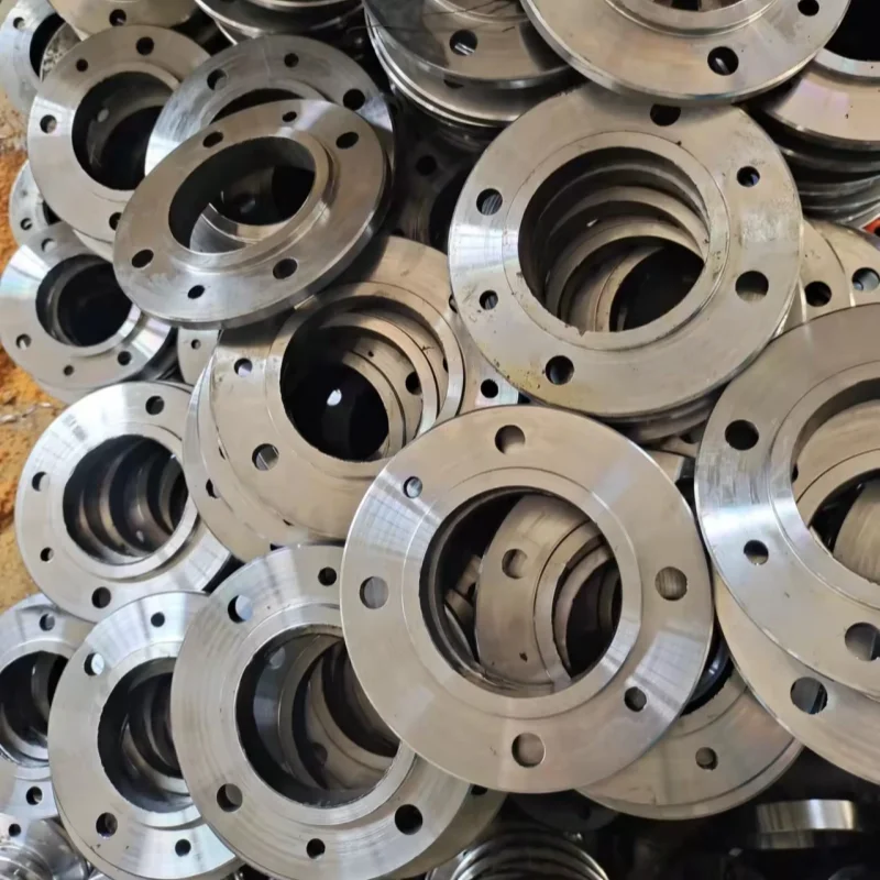
API flange load capacity depends on the loads acting on the complete connection, not just the pressure marked on the flange. Internal pressure, axial tension, and bending can act together. The assessment must also account for geometry, material properties, temperature, bolting, and service conditions.
For wellhead and subsea equipment, the practical question is straightforward: can this specific flange assembly carry the required load combination while maintaining its structural integrity and seal? This guide explains what you need to establish before you can answer that question.
Key Takeaways
- Assess pressure, axial tension, and bending as a combined load case. Separate maximum values do not establish an acceptable combination.
- Match the assessment to the actual flange, mating component, gasket, bolts, and attached pipe or equipment.
- Check a capacity chart’s assumptions before applying it to your connection.
- For subsea duplex stainless steel exposed to cathodic protection, include the applicable HISC assessment.
- Submit drawings and a defined load schedule with your enquiry. A pressure designation alone is insufficient.
What Determines API Flange Load Capacity?
Pressure, Axial Tension and Bending
Internal pressure loads the pressure boundary and creates a separating force at the joint. Axial tension pulls along the connection axis. A bending moment loads the joint unevenly, increasing demand on one side relative to the other.
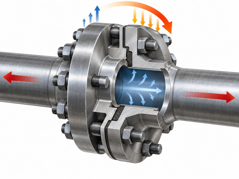
These actions need a common assessment basis. A flange that is acceptable under pressure alone may need further review when connected equipment introduces external loads. Do not assume that the maximum pressure, maximum tension, and maximum bending values from separate calculations can all be applied simultaneously.
API’s published overview of API TR 6AF2 describes the assessment of integral flange capacity under pressure, end tension, bending, and makeup forces, including temperature effects. Its scope illustrates why a pressure-only check does not answer every load-capacity question.
Why API Flange Ratings Are Only a Starting Point
A pressure rating helps identify the connection required for the specified service. It does not, by itself, state the allowable external bending moment or axial load for your installed assembly.
If you are still identifying the pressure designation, start with the API flange ratings guide. For a combined-load review, take the next step: establish which forces occur together, where they act, and which operating conditions they represent.
Tip: Ask for a result tied to a stated pressure, temperature, and load combination, rather than a single unexplained “maximum capacity.”
API 6A Flange Details Needed for a Capacity Review
Connection Type and Actual Dimensions
Record the connection type, nominal size, and pressure designation exactly as shown on the drawing. An API 6B flange and an API 6BX flange must be assessed using the geometry and assembly conditions applicable to that connection.
For identification background, see the difference between API 6B and 6BX flanges. Once the connection is identified, the capacity review should use its drawing revision rather than a generic product image.
API flange dimensions matter beyond the bolt pattern. The reviewer may need the actual bore, flange thickness, hub profile, ring groove, and adjoining wall thickness. Include the mating component and any transition, weld, or local modification that affects the load path.
The API flange sizes guide provides selection background. Submit the project drawing to resolve the dimensions used in the assessment; a nominal size alone does not describe the complete joint.
Material Properties and Temperature
State the specified material grade and condition for each pressure-containing component and for the bolting. Include available material certificates and the temperature range used in the design basis.
Descriptions such as “high-strength alloy” or “superior corrosion resistance” do not provide calculation inputs. The reviewer needs the relevant mechanical properties, their temperature basis, and any service restrictions. The API flange material selection guide covers the broader selection topic; here, the task is to connect the selected material to the actual assessment inputs.
Bolting, Gasket and Assembly Conditions
Identify the bolt or stud grade, size, quantity, coating, and lubricant, together with the specified ring gasket. Provide the approved tightening method and intended preload where these are available.
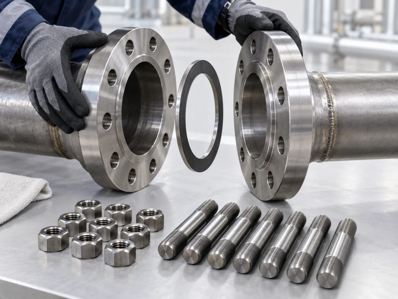
Do not select a universal preload percentage or borrow a torque value from an unrelated assembly. Torque is a means of achieving bolt tension, and the relationship depends on the assembly conditions. Any API flange bolt torque chart used for installation must match the specified fasteners, lubrication, and approved procedure.
Note: Manufacturing accuracy does not remove loads introduced by the installation. Record alignment requirements, support positions, and any imposed displacement that the assessment needs to consider.
When Is an API Flange Chart Applicable?
An API flange chart can mean a dimensional table, a pressure-rating reference, or a combined-load capacity chart. Confirm which one you have before using it. Dimensions help identify a connection; they do not establish an external load limit.
For a capacity chart, record its source, edition, flange configuration, and assumptions. Check the material basis, temperature conditions, makeup assumptions, and acceptance criteria. API’s TR 6AF2 publication overview describes particular analysis and temperature assumptions, so its published results should not be treated as unrestricted limits for every flange assembly.
Request a project-specific engineering review when the connection or load case falls outside the selected method’s scope. Examples include modified geometry, different material properties, uncertain assembly conditions, or additional loads not addressed by the reference.
The review should identify whether calculations, finite element analysis, or other evidence are required. A finite element model is useful only when its geometry, boundary conditions, contacts, preload, and acceptance criteria represent the problem being assessed.
Subsea API 6BX Flanges: Cathodic Protection and HISC
For a subsea connection, identify the material and corrosion-protection arrangement before applying additional assessment rules. These conditions determine whether hydrogen-induced stress cracking, or HISC, needs specific consideration.

DNV-RP-F112 covers components made from duplex stainless steels that are installed subsea and exposed to cathodic protection. This is a defined material-and-environment scope, not a blanket rule for every API flange.
Where that scope applies, provide the material specification, relevant manufacturing records, and cathodic-protection design information to the responsible engineer. Any stress or strain limits must come from the applicable document and project basis. A general statement such as “use two-thirds of yield strength” is not a substitute for that review.
What to Submit for an API Flange Capacity Assessment?
Prepare one consistent package so that the reviewer can connect every load case to the correct assembly. The following checklist is a starting point for an engineering enquiry, not a declaration that the design is approved.
- Connection identification: equipment tag, flange type, nominal size, pressure designation, and governing specification.
- Drawings: current assembly and detail drawings, mating connection, bore, hub, wall thickness, gasket groove and modifications.
- Material data: component and bolting specifications, material condition, traceability and available certificates.
- Pressure and temperature: design, operating and test conditions, plus relevant transient conditions.
- External loads: axial force, bending moments and any shear or torsion, with units, directions and the point of application.
- Load combinations: which loads act simultaneously during installation, operation, testing and other project-defined cases.
- Assembly data: gasket identification, bolting, lubrication, tightening procedure and specified preload.
- Service and acceptance basis: fluid conditions, subsea exposure, cathodic protection where relevant, cyclic duty, applicable document editions and required deliverables.
Keep units and sign conventions consistent. If a load is unavailable, label it as missing; do not enter zero unless zero is an established condition. Ask the reviewer how pressure-induced end loads are treated so they are not inadvertently counted twice.
Example: Turning an Incomplete Enquiry into a Reviewable Request
Consider a hypothetical enquiry for a 7 1/16-inch, 10,000-psi API 6BX connection on a supported equipment assembly. The buyer asks whether it can carry an attached spool. This is an illustrative information request, not an AlienFrac project record or an approved configuration.
The size and pressure designation identify only part of the problem. The review still needs the spool arrangement, support locations, component weights, operating conditions, and calculated forces and moments at the flange. It also needs the connection drawings and assembly data.
A more useful request is: “Please review the attached flange assembly against the operating and installation load cases in our load schedule. Identify missing inputs, the assessment method, acceptance criteria, and any restrictions on the result.”
This gives the reviewer a defined task without assuming a load limit that has not been established.
What a Useful Assessment Result Should Include?
Ask for a report that identifies the drawing revision, load cases, method, material basis, and assembly assumptions. The conclusion should state which cases are acceptable, which criteria govern, and which limitations remain.
A pressure-test record, dimensional inspection report, or material certificate supports a particular part of the evidence package. None should be presented as a stand-alone demonstration of every external load combination. Keep the assessment connected to the configuration that will actually be supplied and installed.
If a case is unacceptable, request a documented review of the available changes, such as support arrangement, imposed loads, or connection design. Reassess the revised configuration before relying on the result.
Discuss Your API Flange Requirements with AlienFrac
Preparing a flange enquiry for wellhead, manifold or pressure-control equipment? Review AlienFrac’s API 6A flange specifications and enquiry details and send your connection size, pressure designation, material requirements, drawings, and service conditions.
If your project requires combined-load verification, state that requirement explicitly and include the load schedule. Ask for confirmation of the available documentation, engineering review scope, and any additional information needed before placing the order. A clear enquiry helps keep product selection, supply documentation, and project approval aligned.