
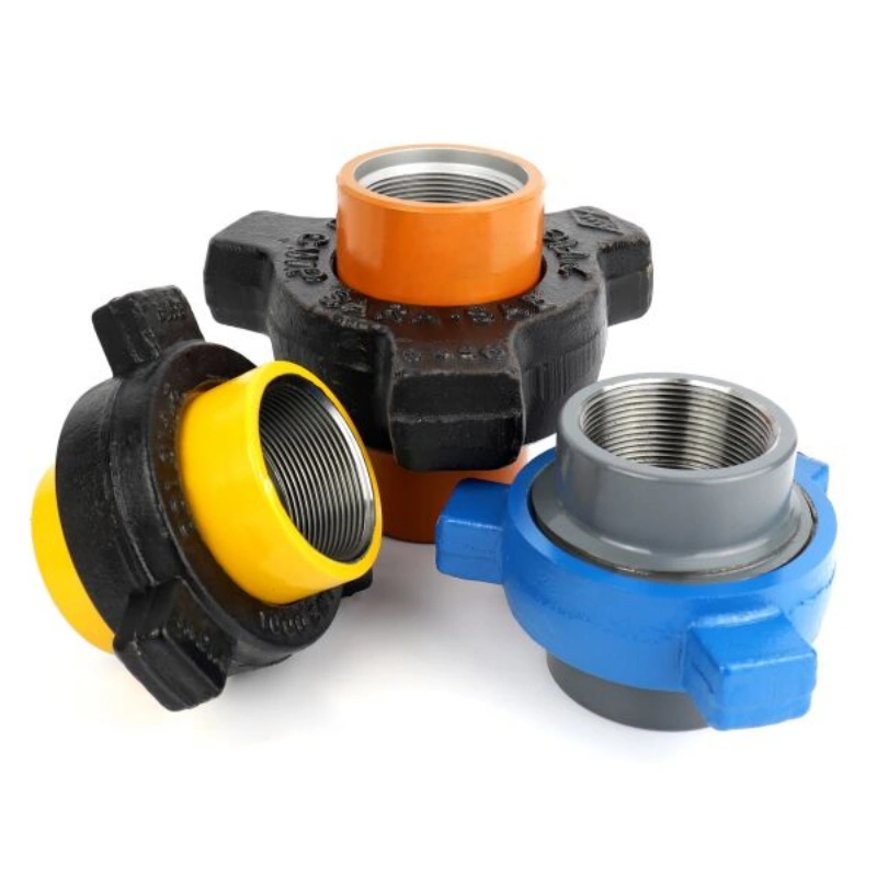
Choosing the right hammer union figure is not a matter of matching a color or picking the highest pressure number on a catalog page. The figure number identifies a product configuration and pressure class, but the safe choice still depends on nominal size, working pressure, fluid, temperature, seal design, end connection, material condition, and the complete assembly.
This guide explains the main hammer union figure types used in oilfield and industrial service, how FIG 100, 200, 206, 400, 602, 1002, 1502, and 2202 differ in practical terms, and how to build a purchase specification that a supplier can quote without guessing. If you need the basic definition first, see what a hammer union is before using this selection guide.
For clarity, “figure types” in this article means FIG-numbered hammer union configurations. Threaded, butt-weld, socket-weld, male, and female describe end-connection options and should not be treated as interchangeable with the FIG classification itself. See the separate hammer union connection types guide when the connection geometry is the main question.
Key Takeaways
- Start with the system’s maximum working pressure, surge duty, temperature, fluid, and nominal size. A higher figure is not automatically the correct figure.
- Treat the figure number, color marking, seal, nut, subs, and end connection as one traceable assembly. Do not mix components simply because they look similar.
- Working pressure controls normal operation. Test pressure is a controlled verification value, not an operating allowance, and burst pressure is destructive evidence rather than a usable rating.
- FIG 602 and FIG 1502 are not interchangeable selections: their pressure classes, seal arrangements, dimensions, and applications can differ materially.
- For sour service, check the complete service envelope and the metallurgy or seal qualification. “NACE” or “H2S resistant” by itself is not a complete product specification.
- Use the current drawing and data sheet for final values. Field color coding helps identification, but stamped markings and approved documentation control the decision.
What Does a Hammer Union Figure Number Mean?
A hammer union is a quickly assembled pressure connection made from mating subs, a seal or sealing surfaces, and a nut that brings the parts together. The figure number is a shorthand for a defined design family. It can indicate the intended pressure class, sealing concept, dimensions, and typical service, but it does not replace the manufacturer’s full specification.
The same figure label may appear across multiple manufacturers or product generations. Small differences in size, material, seal, end preparation, and pressure basis can change the approved use. That is why a purchase order should name the figure, nominal size, working pressure, connection ends, material, seal, applicable standard, inspection requirements, and the required documentation package.
For a field identification workflow, use the hammer union markings guide together with the manufacturer’s drawing. The marking should confirm the figure and pressure class; it should not be inferred from paint alone.
Hammer Union Figure Types at a Glance
The table below is a selection map, not a substitute for an approved data sheet. “Typical role” describes how these figure families are commonly positioned in oilfield service; exact ratings and sizes must be checked for the specific product and configuration.
| Figure | Typical role | Selection note | Typical applications | Product page |
|---|---|---|---|---|
| FIG 100 | Lower-pressure or utility-style service in selected systems | Confirm the exact working pressure, seal design, and end preparation; do not transfer ratings from another supplier. | Water, test, or lower-pressure transfer duties where the product data sheet permits | FIG 100 |
| FIG 200 | Medium-pressure service and general oilfield connections | Check figure-specific pressure basis, bore, and seal arrangement. The 200 label alone is not enough for ordering. | General flowline, mud, cement, or service connections depending on configuration | FIG 200 |
| FIG 206 | Specialized medium-pressure or legacy-compatible configurations | Confirm mating parts, interchangeability, and the exact pressure class before replacing an existing union. | Selected flowline and service equipment | FIG 206 |
| FIG 400 | Higher-pressure service than lower-class utility figures | Verify size-dependent rating, seal, color marking, and material condition against the current drawing. | Oilfield flowlines and pressure service where approved | FIG 400 |
| FIG 402 | 2-inch hammer union configuration with an NBR seal ring | Confirm the required working pressure, connection details, material, and service conditions for the specific application before ordering. | Applications requiring a 2-inch FIG 402 connection where the approved specification matches the service requirements | FIG 402 |
| FIG 602 | Medium-to-high pressure oilfield service; AlienFrac comparison content lists a 6,000 psi working class for its FIG 602 | The current product data sheet controls. Confirm test pressure, seal type, size, color, and sour-service scope. | Manifolds, mud delivery, circulating lines, well service, and high-pressure flowline applications | FIG 602 |
| FIG 1002 | High-pressure service; commonly treated as a 10,000 psi class in product literature | Confirm working/test pressure, size range, seal, and product-specific qualification before release. | High-pressure oilfield flowlines and selected fracturing or cementing systems | FIG 1002 |
| FIG 1502 | High-pressure service; AlienFrac’s current product page lists 15,000 psi NSCWP and 22,500 psi test pressure for its FIG 1502 | Blue nut/red parts are an identification aid only. Confirm the stamped figure, seal, size, and full assembly rating. | Cement filling, fracturing, acidizing, testing, and choke-and-kill lines where approved | FIG 1502 |
| FIG 2202 | Ultra-high-pressure service in selected product ranges | Treat the exact pressure, size, seal, and application as engineering-controlled values; do not assume every 2202 union has the same rating. | Specialized high-pressure and ultra-high-pressure systems | FIG 2202 |
Important: The figures and roles above are a practical comparison framework. Before publication, reconcile every exact rating, dimension, color, seal, material, and certification statement with Alienfrac engineering records. If the page is intended to be a contractual specification, use the approved product drawing instead of this article.
How the Main Figure Types Differ?
FIG 100, FIG 200, FIG 206, FIG 207, and FIG 400
These figure families are often evaluated for lower- to medium-pressure or specialized service, but their names should not be used as a universal pressure chart. Start by checking the marked figure, nominal size, and manufacturer’s pressure table. A replacement union also needs the correct mating geometry and seal arrangement; a similar-looking nut or sub is not proof of interchangeability.
When an existing system uses a legacy figure, record the actual marking, bore, end connection, pressure requirement, and service fluid before proposing a replacement. This is especially important when the union is installed in a manifold or hose assembly where the weakest component controls the safe working limit.
For a related configuration, FIG 207 uses a threaded connector that is interchangeable with the corresponding threaded connectors of FIG 200 and FIG 206. Confirm the exact figure, size, connection arrangement, and approved service requirements before selecting a replacement.
FIG 602
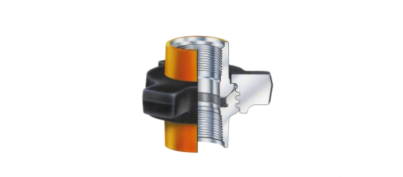
FIG 602 is commonly selected for medium- to high-pressure oilfield service. Alienfrac’s current comparison page describes its FIG 602 as a 6,000 psi working-pressure class with a 9,000 psi test pressure and a lip-type seal with a secondary metal-to-metal seat. Those values belong to the referenced product configuration; confirm them against the current drawing before publishing or ordering.
Use FIG 602 when the application needs a pressure class above conventional lower-pressure unions but does not require the same selection basis as a FIG 1502. For a focused comparison, see FIG 602 vs FIG 1502.
FIG 1002
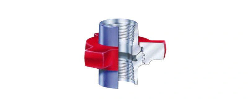
FIG 1002 is generally positioned for high-pressure oilfield service and is often associated with a 10,000 psi working-pressure class. Confirm the exact pressure basis, because working pressure, test pressure, and any temperature or service derating must be stated for the complete assembly. Check the seal, end connection, nominal size, and required standard together rather than ordering from the figure number alone.
FIG 1502
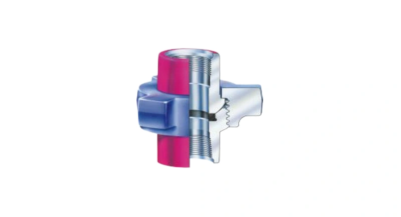
FIG 1502 is a high-pressure hammer union used in demanding oilfield operations. The current Alienfrac FIG 1502 product page lists 15,000 psi NSCWP and a 22,500 psi test pressure for its configuration, with a replaceable resilient seal ring and blue nut/red parts. The page also identifies cement filling, fracturing, acidizing, testing, and choke-and-kill lines as typical applications.
The practical lesson is simple: do not select a 1502 because it is the highest number on a shortlist. Select it when the system pressure, fluid, temperature, connection geometry, seal, and operating duty match the approved product configuration. The hose, valve, flange, pup joint, and mating union must all be rated and qualified for the same service envelope.
FIG 2202 and Other Ultra-High-Pressure Figures
Ultra-high-pressure figure families are used only when the application and the complete pressure boundary require them. A larger figure number can bring different dimensions, handling requirements, sealing details, and inspection controls. It can also create a mismatch with existing equipment if the mating parts were designed for another figure.
For a FIG 2202 request, send the complete pressure-temperature envelope, nominal size, fluid, connection ends, cycle duty, material requirements, and documentation requirements. Ask the supplier to confirm the exact working pressure and test basis in writing.
Figure Comparison: What to Record Before Ordering
A useful hammer union figure chart does more than list numbers. It should capture the details that change the engineering decision and the quotation scope.
| Check | What to specify | Why it matters |
| Figure and marking | Exact FIG number, manufacturer or style, stamped pressure class, nut/sub marking, and revision of the reference drawing | Prevents a color- or appearance-based substitution. |
| Nominal size and bore | Line size, bore, wall, overall length, and dimensional tolerances | Controls flow, fit, weight, and connection alignment. |
| Pressure basis | Rated working pressure, surge/pulsation, proof/test pressure, and any derating | Keeps operating limits separate from test or destructive values. |
| Seal and sealing surfaces | Seal material, lip or resilient ring, metal-to-metal seat, replacement kit, and compatibility | Affects leak tightness, maintenance, and chemical service. |
| End connections | Threaded, butt-weld, socket-weld, flanged, male/female, orientation, and schedule or grade | Ensures the union can mate with the existing system. |
| Service environment | Standard service, sour service, H2S/CO2, water phase, temperature, chemicals, solids, and corrosion risk | Determines material and seal suitability. |
| Inspection and records | Material certificates, NDE, hydrotest chart, traceability, marking, and certificate of conformity | Makes the supplied assembly auditable after delivery. |
How to Select the Right Hammer Union Figure?
1. Start With the Maximum Working Pressure
Record normal pressure, maximum working pressure, expected surge, pulsation, and the approved test pressure separately. The union is only as safe as the lowest-rated component in the pressure boundary. That can be the seal, hose end, valve, flange, weld, pup joint, or mating union rather than the nut itself.
Use the dedicated hammer union pressure ratings guide when the rating is the main question. For quick field checks, the pressure ratings and color codes guide can support identification, but the stamped marking and data sheet remain the controlling references.
2. Match the Nominal Size and Flow Requirement
Confirm both the nominal pipe or hose size and the required internal bore. A nominal size match does not guarantee that the bore, length, wall, or end geometry is correct. Check the mating equipment drawing and allow for installation clearance, wrench access, bend radius, and the space needed for inspection or seal replacement.
3. Check the Fluid, Temperature, and Duty Cycle
Oilfield service can include drilling mud, cement slurry, acid, hydrocarbons, water, gas, or multiphase fluids. Abrasive solids, chemical additives, temperature swings, vibration, and pressure cycling may change the correct seal and material. A union suitable for static liquid service may not be suitable for hot gas, sour fluid, or repeated pulsation.
4. Select the Seal and Material as a System
The sealing element and metallic parts must be compatible with the fluid and with one another. Review seal compound, hardness, temperature range, chemical exposure, sour-service requirements, corrosion allowance, heat treatment, hardness limits, and any welding or coating condition. A “corrosion-resistant” label is not enough without the grade and service limits.
5. Confirm the End Connection
Threaded ends are convenient for removable equipment, while butt-weld ends can suit permanent or high-integrity piping arrangements. Socket-weld, flanged, male, and female options can also be available depending on the figure and supplier. Match thread form, size, pressure class, bore, orientation, weld schedule, and inspection requirements.
The end connection is a separate selection dimension from the FIG number. Use the hammer union connection types guide for the connection comparison, and the male and female identification guide when the existing equipment is not clearly marked.
6. Request the Evidence You Need to Approve the Purchase
For a production or critical-service order, request the controlled drawing, data sheet, material certificates, seal information, inspection and test plan, hydrostatic test record, NDE reports where required, certificate of conformity, serial-number traceability, and installation or maintenance instructions. Add third-party inspection, witness points, or special sour-service evidence when the project specification requires them.
Standard Service vs Sour Service / H2S Considerations
Standard-service and sour-service hammer unions should not be selected by the same shortcut. In H2S-containing service, the fluid composition, H2S partial pressure, water phase, temperature, material strength, hardness, stress, and exposure time can affect the risk of cracking or seal degradation.
The relevant assessment applies to the complete wetted assembly, not just the external color or a generic material name.
For metallic parts, request the applicable sour-service material basis and confirm that it covers the exact material condition, heat treatment, hardness, manufacturing route, and environmental limits. For seals, confirm the actual compound and exposure evidence.
NACE MR0175/ISO 15156 may support metallic material selection in relevant upstream environments, but a NACE statement alone does not certify every elastomer, the complete union, or every downstream application.
Do not overstate: Avoid publishing “all hammer unions are H2S resistant”, “NACE certified” without scope, or “compatible with every sour-gas application”. State the tested or approved service envelope and its exclusions.
Threaded vs Butt-Weld Ends
Threaded hammer unions are useful when the connection must be assembled and removed in the field. They require exact thread compatibility, correct alignment, clean sealing surfaces, and the approved installation method. Butt-weld ends create a more permanent connection and can reduce the number of threaded leak paths, but they introduce welding, heat input, inspection, dimensional, and repair controls.
Neither end type is universally better. Select the connection based on pressure class, maintenance plan, fabrication capability, access, field replacement needs, applicable standard, and the mating equipment. Keep the discussion here brief so this page remains about figure types; send readers to the dedicated connection-types page for the detailed comparison.
Common Hammer Union Selection Mistakes
- Choosing by color only. Color helps a field crew recognize a product quickly, but color systems are manufacturer- and figure-specific. Confirm the stamp and documents.
- Treating test pressure as working pressure. A hydrostatic test value is not permission to operate at that pressure.
- Mixing figures or components from different suppliers without an approved interchangeability basis. Similar threads or a matching nut do not prove matching seals or pressure integrity.
- Ignoring temperature derating. Pressure capability can change with temperature, fluid, seal material, and service duration.
- Ordering a “1502” or “602” without a nominal size, end connection, material, seal, and documentation scope.
- Assuming a general NACE, API, or ISO statement covers the complete assembly, every material, and every service condition.
- Failing to inspect sealing surfaces, threads, nut condition, and seal rings before installation or after an abnormal pressure event.
Installation and Inspection Basics
Before assembly, isolate and depressurize the line, verify the figure and size, clean the threads and sealing surfaces, inspect the seal, and confirm that the mating parts are not damaged or mismatched. Follow the manufacturer’s assembly procedure and torque or hammering limits. Never use force to compensate for a misaligned thread or an incorrect part.
During service, inspect for leakage, corrosion, washout, thread damage, nut movement, seal extrusion, cracks, deformation, and damage caused by vibration or impact. After a pressure surge, fire, chemical exposure, or other abnormal event, remove the union from service until the responsible engineer or manufacturer confirms its fitness. Record inspections and replacement seals so the assembly remains traceable.
For the full procedure, link to hammer union installation and hammer union parts.
Conclusion: Choose the Figure That Matches the Whole Assembly
The best hammer union figure is the one that matches the system’s pressure, size, fluid, temperature, movement, seal, end connection, material, and documentation requirements. FIG 602, FIG 1002, FIG 1502, and FIG 2202 may all be high-pressure options, but they are not interchangeable by number alone. Lower or specialized figures such as FIG 100, FIG 200, FIG 206, and FIG 400 also require product-specific confirmation.
Use the figure number to narrow the search, then verify the complete data sheet and mating assembly. If the requirement involves sour service, high-pressure gas, acidizing, fracturing, choke-and-kill, or a non-standard connection, provide the full service envelope before the quotation is finalized.
Send Alienfrac your nominal size, maximum working pressure, fluid and temperature, figure or existing marking, end connections, service type, quantity, and documentation requirements for a figure-specific review.
FAQ
What is the difference between hammer union types and figure types?
Hammer union types is a broad phrase that can refer to figure families, pressure classes, seal designs, or end connections. Figure types are the FIG-numbered configurations such as FIG 602 or FIG 1502. Threaded, butt-weld, male, and female describe connection details and should be specified separately.
Is FIG 1502 always rated at 15,000 psi?
Not every product carrying a 1502 label should be assumed to have the same rating without checking its manufacturer and configuration. Alienfrac’s current FIG 1502 product page lists 15,000 psi NSCWP and 22,500 psi test pressure for its stated configuration. Confirm the current data sheet, size, temperature, and service derating before ordering.
What is the difference between FIG 602 and FIG 1502?
The main differences are pressure class, seal arrangement, dimensions, color marking, and typical application. Alienfrac’s comparison content lists FIG 602 at 6,000 psi working pressure and FIG 1502 at 15,000 psi, but the approved product documentation controls the final selection.
Can I use a hammer union with a different manufacturer’s mating part?
Do not assume interchangeability from the figure number or appearance alone. Confirm the mating standard, dimensions, threads, sealing surfaces, pressure class, materials, and the supplier’s written interchangeability basis. When in doubt, replace the complete matched set.
Are hammer union colors standardized?
Color coding is useful for quick identification, but it is not a universal substitute for markings and documents. Color conventions can differ by figure, manufacturer, product generation, or service. Verify the stamped figure and pressure class before assembly.
What information should I include in a hammer union RFQ?
Include figure or existing marking, nominal size and bore, working and test pressure, surge duty, fluid, temperature, sour-service requirements, material, seal, end connection, quantity, delivery date, inspection level, and required certificates or traceability records.